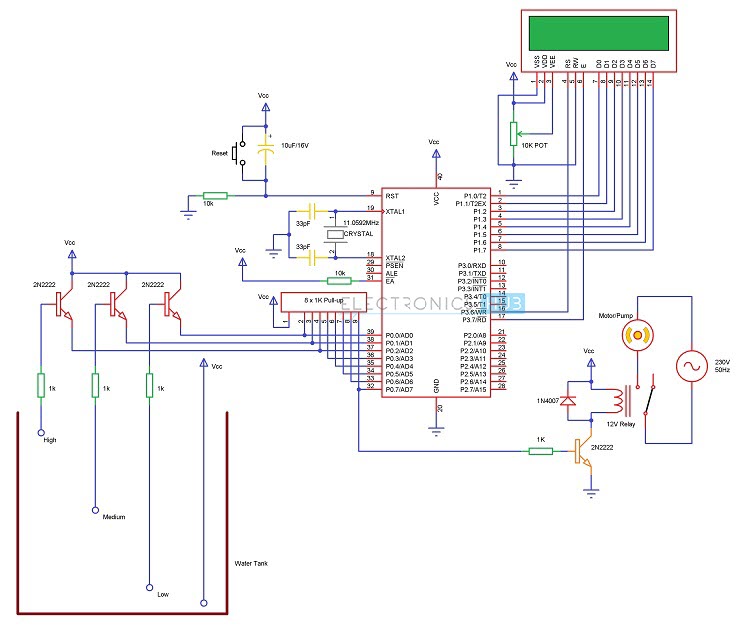
The motor is switched OFF when the overhead tank or container is FULL. Here, the water level of the tank is indicated on LCD (Liquid crystal Display). Using this system, we can avoid the overflow of the water. We have already seen How water level indicator circuit works using AVR Microcontroller in the earlier post. But, here we are designing the circuit which is used to detect and control the water level automatically in overhead tank using 8051 microcontroller. In this system, water sensing can be done by using a set of 4 wires, which are placed at different levels in tank. DC supply probe is placed at the base of the tank.
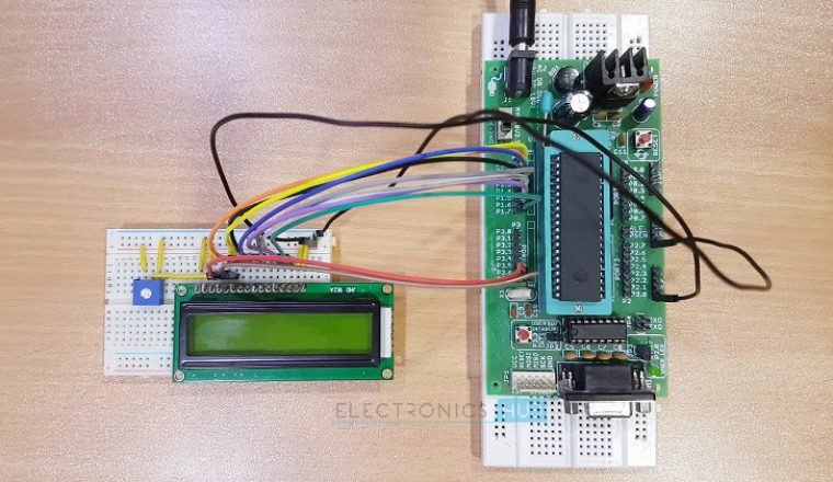
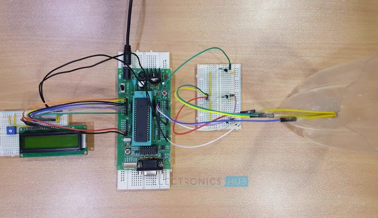
Construction and Output Video
Water Level Controller using 8051 Circuit Principle
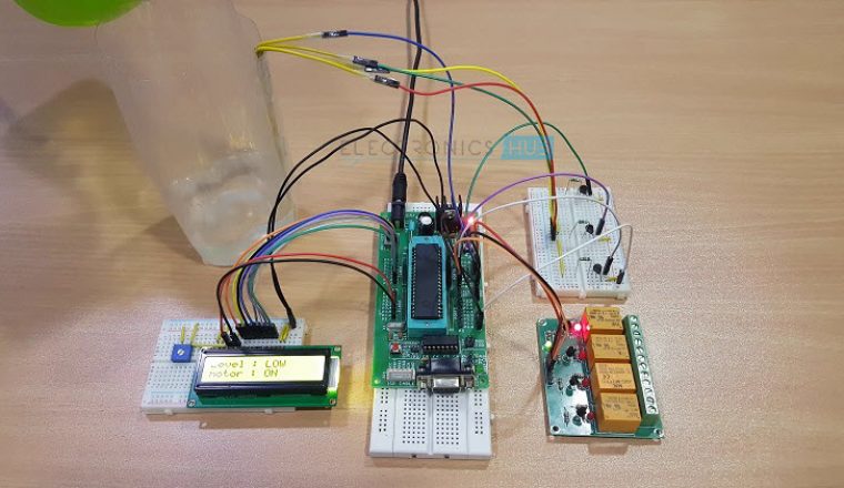
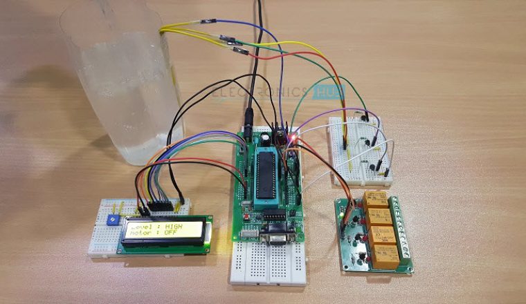
This system mainly works on a principle that “water conducts electricity”. The four wires which are dipped into the tank will indicate the different water levels. Based on the outputs of these wires, microcontroller displays water level on LCD as well as controls the motor. Initially when the tank is empty, LCD will display the message LOW and motor runs automatically. When water level reaches to half level, now LCD displays HALF and still motor runs. When the tank is full, LCD displays FULL and motor automatically stops. Again, the motor runs when water level in the tank becomes LOW.
Water Level Controller using 8051 Microcontroller Circuit Diagram
Components Required for Water Level Controller using 8051 Microcontroller
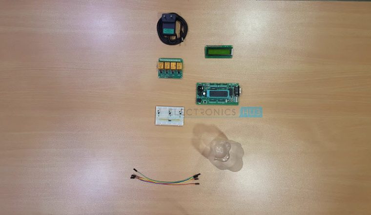
AT89C51 Microcontroller (or any 8051 based Microcontroller) 8051 Programmer (Programming Board) 11.0592 MHz Quartz Crystal 2 x 33pF Capacitor 2 x 10KΩ Resistor (1/4 Watt) 10µF Capacitor Push Button 1KΩ x 8 Resistor Pack (for Pull – up) 16 x 2 LCD Display 5V Relay 4 x 2N2222 (NPN) Transistors DC Motor (for demonstration) 10KΩ Potentiometer 1N4007 PN Junction Diode Programming cable Connecting wires Power Supply Keil µVision IDE Willar Software (for burning code) Proteus (for circuit diagram)
How to Design Circuit for Water Level Controller using 8051 Microcontroller?
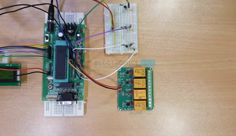
The heart of the Water Level Controller using 8051 Microcontroller project is the AT89C51 Microcontroller. The water level probes are connected to the P0.0, P0.1 and P0.2 through the transistors (they are connected to the base of the transistors through corresponding current limiting resistors). P0.0 for LOW level, P0.1 for HALF Level and P0.2 for HIGH Level. The Collector terminals of the Transistors are connected to VCC and the Emitter terminals are connected to PORT0 terminals (P0.0, P0.1 and P0.2). PORT1 of the microcontroller is connected to the data pins of LCD and the control pins RS, RW and EN of the LCD Display are connected to the P3.6, GND and P3.7 respectively. For demonstration purpose, we have used a simple DC Motor Pump. It is connected to the Relay and the input to the relay is fed from P0.7 through a transistor.
Algorithm for Water Level Controller Circuit
First configure the controller pins P0.0, P0.1 and P0.2 as inputs and P0.7 as output. Now, initialize the LCD. Continuously check the water level input pins P0.0, P0.1 and P0.2. If all the pins are low, then display tank as “EMPTY” on the LCD and make P0.7 pin HIGH to run the motor automatically. If the level is low i.e. if P0.0 is HIGH, display the water level as “LOW” and continue to run the motor. A HIGH pulse on the pin P0.1 indicates that water has reached half level. So, display the same thing on LCD and run the motor normally. If P0.2 is HIGH, then the water level in the tank is FULL. Now, make the P0.7 pin as LOW to turn off the motor automatically.
Water Level Controller using 8051 Circuit Simulation Video
DOWNLOAD PROJECT CODE
How to Operate Water Level Controller Circuit using 8051 Microcontroller?
Water Level Controller Circuit Advantages
Human effort is reduced as the system controls the motor automatically based on the water level. This system consumes less power. Simple and more reliable.
[Also Read: How To Make an Adjustable Timer ]
Applications of Water Level Controller Circuit using 8051
Used in big buildings where the manual monitoring is difficult. Used in industries to control the liquid level automatically.
I wd do the same one so can you help me ? in theme of the hardware and program code? email : iddhamshahlee@gmail.com thanks you Just read the article and got instantly hooked but the source code isn’t showing gives me a site can’t be reached Comment * Name * Email * Website
Δ
![]()
![]()
![]()

![]()
![]()

