Circuit Diagram of Security Alarm:
Circuit Components:
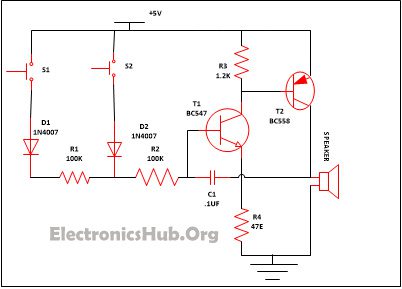
Resistor R1, R2 (100K) – 2 R3 (1.2K) – 1 R4 (47E) – 1 T1 (BC547) – 1 T2 (BC558) – 1 D1, D2 (1N4007) – 2 C1 (. 1uf) – 1 S1, S2 – 2 Speaker – 1
Working of Security Alarm Circuit:
S1 and S2 are the two switches that are used in the circuit so that both can be put in two different places i.e. one of them can put in front of the locker while another one can be placed on the front door. When the switch S1 is pressed diode D1 which is linked with it starts conducting as the transistor T1 and T2, which is attached with the resistor begin its conduction. For the oscillation purpose Transistor T1 and T2 gets a positive feedback which is provided by capacitor C1. The presence of any intruder is indicated by the low tone frequency which is generated when switch S1 is pressed. Same kind of condition occurs when switch S2 is pressed. Diode D2 which is linked with the switch S2 begin its conduction and offers power supply the transistor T1 and T2, which is in the waking state and as a result sound comes from the speaker attached to it. But in this instance a high frequency tone comes out which is a sign that there is some intruder present around the locker. The sound that came from the speaker can only be stopped by cut off the power supply. Comment * Name * Email * Website
Δ
![]()
![]()
![]()
![]()
![]()

