The robot senses the surroundings through the CCD camera and sends to the receiver through the Radio Frequency wireless communication. We have already studied how to establish RF communication in RF Remote Control Circuit for Home Appliances post. This circuit is also designed using such kind of technology.
Remote Operated Spy Robot Circuit Principle:
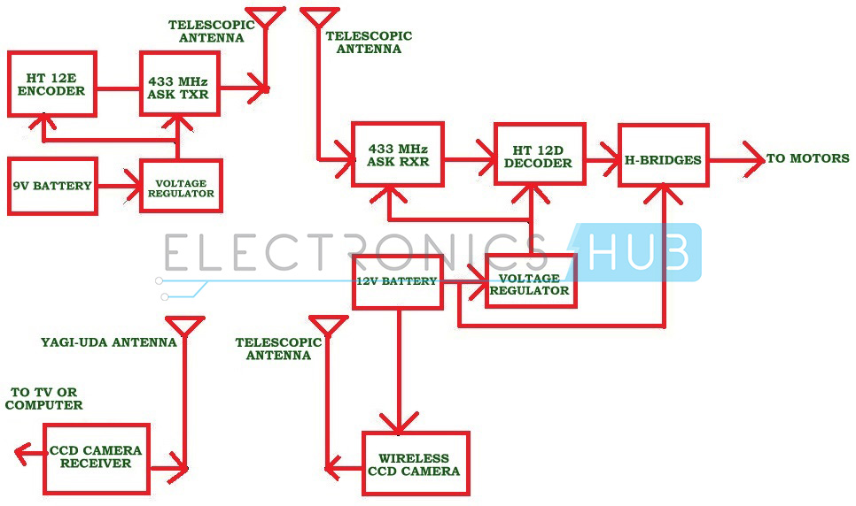
When we press any key in remote, the HT12E encoder generates 8 bit address and 4 bit data. Then ASK (Amplitude shift keying) transmitter sends 8 bit address and 4 bit data to the receiver. At the remote section DIP (dual inline package) switches are used to set 8 bit address. Receiver receives these 12 bit data and gives it to the HT12D decoder to decode the data. The decoded data is given to the L293D motor driver to rotate the robot motors.
Block Diagram of Remote Operated Spy Robot:
Circuit Components:
HT12E encoder HT12D decoder RF 433 MHz Transmitter and Receiver L293D motor driver Wireless CCD camera push buttons – 4 DC battery – 12V, 1.3 Ah 9V DC battery Robot Resistors – 33k,750k SPST switch – 1 NOT gates – 4
Remote Operated Spy Robot Circuit Diagram and Design:
Remote operated spy robot has mainly two sections, one is remote control section used to control the robot and other one is video transmission section used to transmit audio and video information.
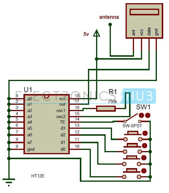
Remote Control Section:
Here HT12E encoder reads the parallel data from the switches and gives this data to the RF transmitter serially. The operating voltage of this encoder is 2.4 to 12V. The RF 434 MHz Transmitter output is up to 8mW at 433.92 MHz frequency. This ASK transmitter accepts both linear and digital inputs and operating voltage is 1.2V to 12V DC. In remote section, SW1 is used to enable the transmission.
Video Transmission Section:
In this section, major components are wireless camera, RF receiver and Robot. Wireless CCD Camera: The operating voltage of CCD camera is 12V DC. The supply for this camera is taken from the motors battery. The output signals of this camera are in the form of audio and video. These types of cameras are commonly available in the market.
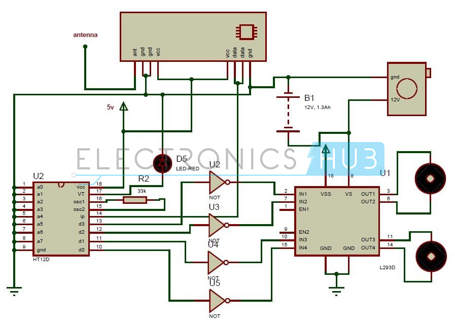
RF Receiver:
ASK receiver receives the serial data transmitted by the transmitter and gives it decoder to convert it to the parallel. This parallel data is given to the L293D motor driver IC to control the robot motors. Here LED D5 indicates the valid transmission.
L293D Motor Driver:
L293d is a Dual H-bridge motor driver. Used as a current amplifier since it takes low current control signal and provides higher current signal as output. This output signal is used to drive the motors. This IC drives 2 motors simultaneously, both in forward direction and reverse direction. Motor 1 direction can be controlled based on logic inputs at IN1 and IN2. Motor 2 operations are controlled based on the inputs at IN3 and IN4. Here the motors are operated with the voltage applied at pin 8.
IN1=0 and IN2=0 -> Motor 1 idle IN1=0 and IN2=1 -> Motor 1 Anti-clock wise direction IN1=1 and IN2=0 -> Motor 1 Clock wise direction IN1=1 and IN2=1 -> Motor 1 idle IN3=0 and IN4=0 -> Motor 2 idle IN3=0 and IN4=1 -> Motor 2 Anti-clock wise direction IN3=1 and IN4=0 -> Motor 2 Clock wise direction IN3=1 and IN4=1 -> Motor 2 idle
Here Vcc is the voltage applied for the internal operation of IC. VSS is the voltage applied to drive the motors. We can apply a maximum of 36V and 600mA to drive the DC motors. Enable pins EN1 and EN2 of motor driver IC must be high to drive the motors.
How to Operate Remote Operated Spy Robot:
Remote Operated Spy Robot Project Output Video:
Remote Operated Spy Robot Applications:
Remote Operated Spy Robot Limitations:
This system does not work for longer distances. This is a theoretical circuit and may require some changes to implement practically.
Comment * Name * Email * Website
Δ
![]()
![]()
![]()
![]()
![]()

