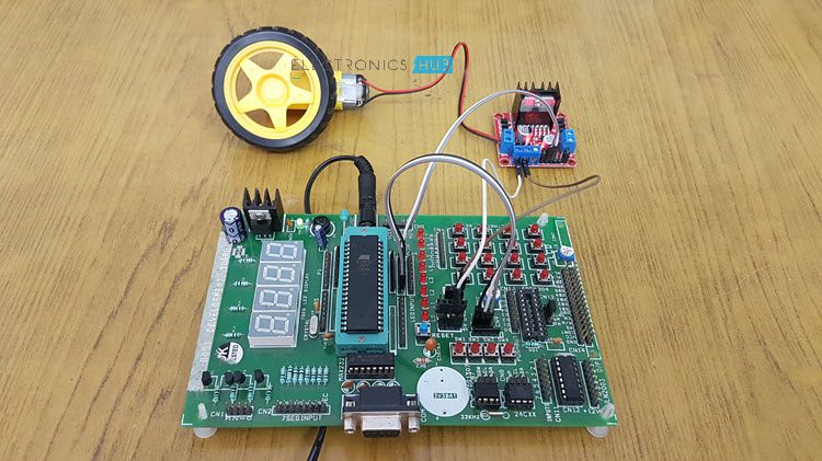
When we talk about controlling the robot, the first thing comes into the mind is controlling DC motors. Interfacing DC motor to the microcontroller is very important concept in Robotic applications. By interfacing DC motor to the microcontroller, we can do many things like controlling the direction of the motor, controlling the speed of the motor. This article describes you how to control the DC motor using AT89C51 controller (or any variant of 8051 Microcontroller).
Circuit Principle
The maximum output current of microcontroller pin is 15mA at 5V. But the power requirements of most of DC motors is out of reach of the microcontroller and even the back emf (electro motive force) which is produced by the motor may damage the microcontroller. Hence, it is not good to interface DC motor directly to the controller. So, we use motor driver circuit in between a DC motor and the microcontroller. Here, we are using L293D and L298N motor driver ICs to drive DC motors. Using these IC’s, we can drive two DC motors at a time. For L293D Motor Driver, the motor supply is variable between 4.5 to 36V and it provides maximum current of 600mA. In case of L298N, the motor supply is up to 46V and it can provide a current of 3A.
A Brief Note on L293D Motor Driver
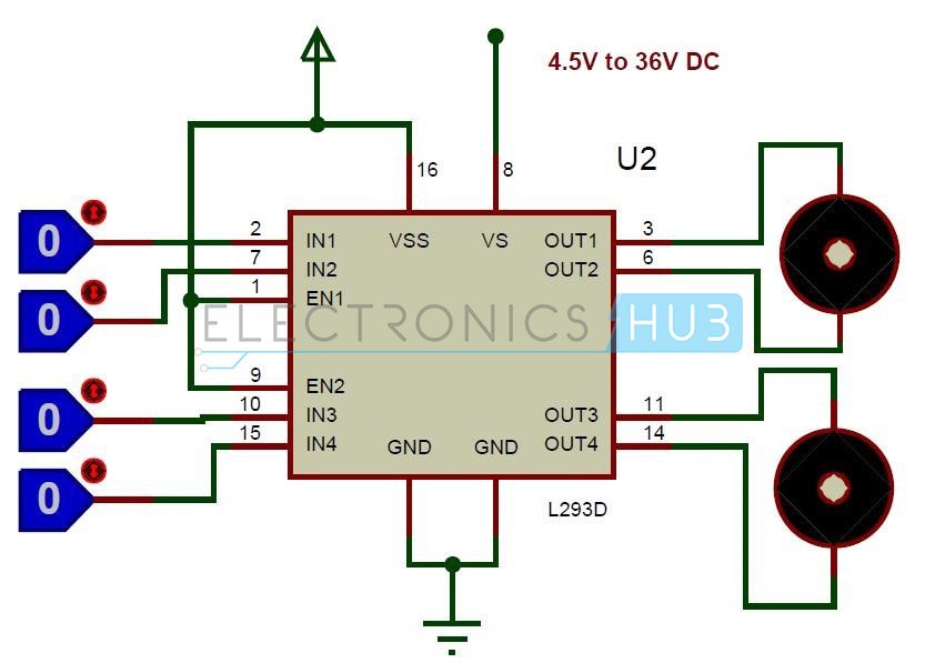
L293D is a quadruple H- bridge motor driver, as the name suggests it used to drive the DC motors. This IC works based on the concept of H- Bridge. H-bridge is a circuit which allows the voltage in either direction to control the motor direction. There are 4 input pins for L293D. Motors directions depends on the logic inputs applied at this pins. EN1 and EN2 must be high to drive the 2 DC motors.
IN1=0 and IN2=0 -> Motor1 idle IN1=0 and IN2=1 -> Motor1 Anti-clock wise direction IN1=1 and IN2=0 -> Motor1 Clock wise direction IN1=1 and IN2=1 -> Motor1 idle IN3=0 and IN4=0 -> Motor2 idle IN3=0 and IN4=1 -> Motor2 Anti-clock wise direction IN3=1 and IN4=0 -> Motor2 Clock wise direction IN3=1 and IN4=1 -> Motor2 idle
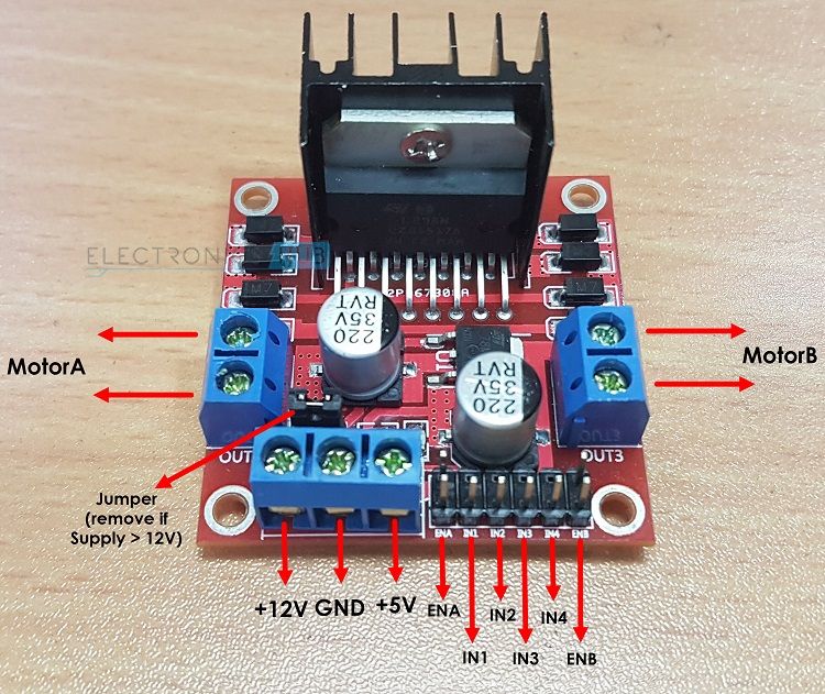
A Brief Note on L298N Motor Driver
The L298N Motor Driver Module is more frequently used driver IC’s now-a-days. The current and voltage ratings of L298N are higher than that of L293D Motor Driver. For more information on L298N Motor Driver Module, refer to the “A BRIEF NOTE ON L298N MOTOR DRIVER“.
Circuit Diagram for Interfacing DC Motor with 8051 Microcontroller and L293D
Components Required
AT89C51 (8051 Microcontroller) 8051 Programmer programming cable 12V DC battery or Adaptor L293D motor driver DC motor Electrolytic capacitor – 10uF 2 Ceramic capacitors – 33pF 10k resistors (1/4 watt) – 4 Push Buttons – 3 Connecting wires.
Circuit Design
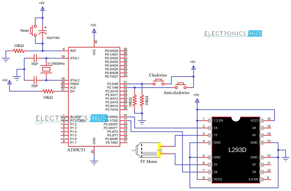
The major components in the above circuit diagram are at89c51 microcontroller and motor driver. Here, the motor driver input pins IN1, IN2 are connected to the P3.0 and P3.1 respectively to control the motor directions. DC motor is connected to output terminals of L293D. EN1 pin is connected to the 5V DC to drive the motor. Switches are connected to the P2.0 and P2.1 of the Microcontroller in pull down configuration. First switch rotates the motor in clockwise direction and second switch rotates the motor in anti clockwise direction. 8th and 16th pins of the motor driver are connected to the +5V supply.
Algorithm
Code
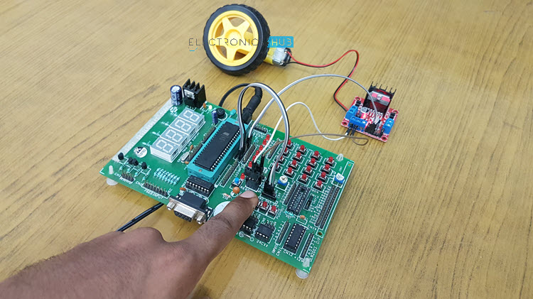
Circuit Simulation Video
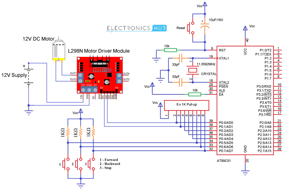
Circuit Diagram for Interfacing DC Motor with 8051 Microcontroller and L298N
Components Required
AT89C51 (8051 Microcontroller) 8051 Programmer Programming cable 12V DC battery or Adaptor L298N Motor Driver Module 12V DC motor Electrolytic capacitor – 10µF 2 Ceramic capacitors – 33pF 10KΩ Resistor (1/4 watt) 1KΩ Resistors (1/4 watt) – 3 8 x 1KΩ Resistor Pack Push Buttons – 4 Connecting wires.
Circuit Design
Similar to the above circuit, the IN1 and IN2 of the L298N Motor Driver are connected to Port 0 Pins P0.0 and P0.1 of the Microcontroller. A 12V DC Motor is conneced at the OUT1 and OUT2 terminals of the Motor Driver Module. In order to control the Motor’s direction of rotation, I will be using three Push Buttons which are connected to Port 0 Pins P0.5, P0.6 and P0.7.
Algorithm
Code
How to Operate?
Applications
This concept is used in robots to control the robot directions. Used to control the speed of the DC motor. It is used in the applications where we need to drive the high voltage motors.
Recommended Readings:
12 Best Drone Kits for Beginners: 2018 Reviews and Buying Advice
please help me Comment * Name * Email * Website
Δ
![]()
![]()
![]()

![]()
![]()

