Output Video
Principle of Ultrasonic Rangefinder
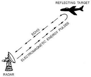
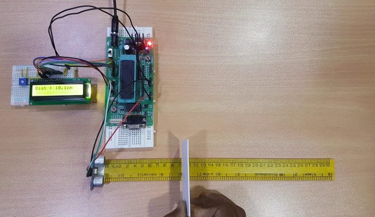
Generally, the distance can be measured using pulse echo and phase measurement method. Here, the distance can be measured using pulse echo method. The ultrasonic module transmits a signal to the object, then receives echo signal from the object and produces output signal whose time period is proportional to the distance of the object. The mechanism of the ultra sonic sensor is similar to the RADAR (Radio Detection and Ranging). This circuit calculates the distance of the object based on the speed of the sound wave at normal temperature and displays the distance on LCD.
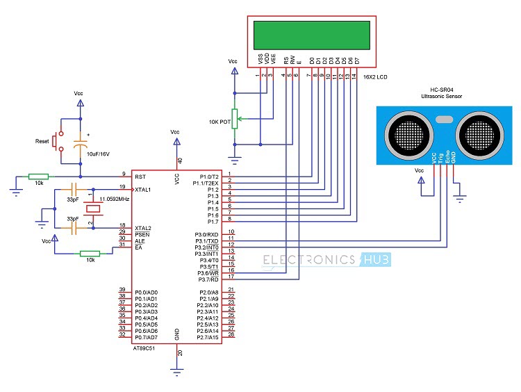
Circuit Diagram of Ultrasonic Rangefinder using 8051
Components Required for Ultrasonic Rangefinder
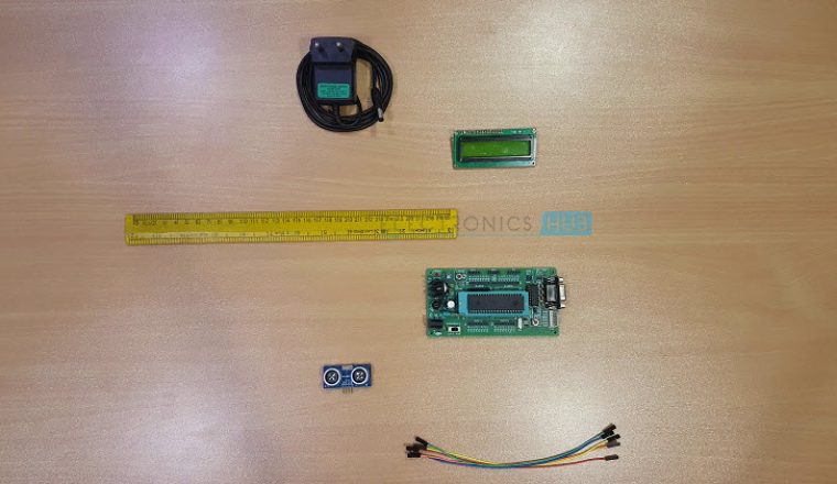
AT89C51 Microcontroller 8051 Programming board Programming cable HC – SR04 Ultrasonic Module 16 x 2 LCD 10KΩ Potentiometer 10µF / 16V Electrolytic Capacitor 2 x 10KΩ Resistor (1/4 Watt) 0592 MHz Crystal 2 x 33pF Capacitors Push Button Connecting wires Power Supply Keil µVision Software Proteus Willar Software
Circuit Design of Ultrasonic Rangefinder
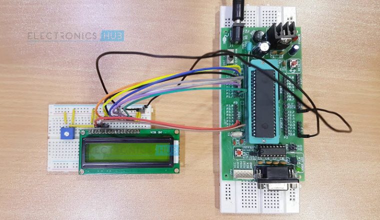
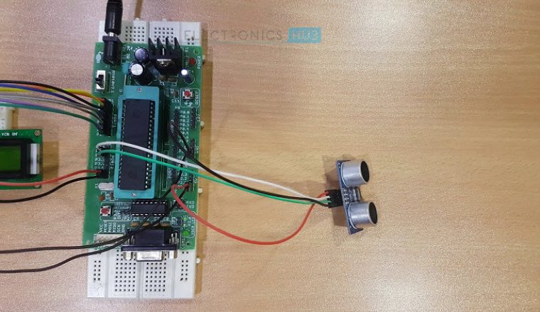
The major components in this project are AT89C51 Microcontroller, Ultrasonic Sensor and LCD Display. The TRIGGER and ECHO pins of the Ultrasonic Sensor are connected to the P3.1 and P3.2 pins respectively. LCD data pins are connected to the PORT1 of the microcontroller and controller pins RS, RW and EN are connected to the P3.6, GND and P3.7 respectively. Here, the LCD (Liquid Crystal Display) is used to display distance of the object. 10KΩ POT is used to vary the contrast of the LCD. Power supply pins of the microcontroller, LCD and Ultrasonic Sensor are connected to the 5V DC. Ultrasonic Module (Ultrasonic Sensor) HC – SR04 Ultrasonic Module works on the principle of SONAR and is designed to measure the range of the object in small embedded projects. It offers excellent range detection with high accuracy and stable readings. The operation of the module is not affected by the sunlight or black material. Features Pin Configuration
How Ultrasonic Rangefinder using 8051 Circuit works?
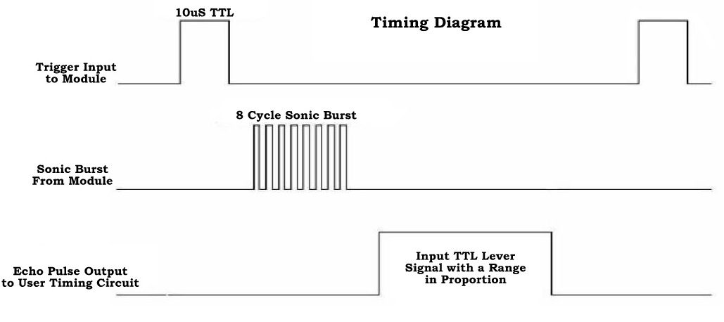
When HIGH pulse of 10µs is applied to the TRIG pin, the ultrasonic module transmits 8 consecutive pulses of 40 KHz. after transmitting 8th pulse the ECHO pin of the sensor becomes HIGH. When the module receives reflected signal from the object, the ECHO pin becomes LOW. The time taken by the signal to leave and return to the sensor is used to find out the range of the object. Distance in centimeters = (Time/58) Object distance in inches = (Time/148) Distance can also be calculated using speed of the ultrasonic wave 340m/s
Download Project Code
Algorithm for Program
Initially P3.1 = 0; P3.1 = 1; delay_ms (10); P3.1 = 0; while (INT0 == 0); while (INT0 == 1); Time required = TIMER0 VALUE/2 Range = 17015 * TIMER0 X 10-6
How to Operate?
Ultrasonic Rangefinder Project Applications
Used to measure the obstacle distance. This system used in automotive parking sensors and obstacle warning systems. Used in terrain monitoring robots.
Limitations of the Circuit
This system is not able to measure longer distances.
thank you Nikhil Shetty 2.Are you trying to make the same project or different one? No. Because our project required us to use two microcontroller boards with some other different components. And besides, my microcontroller board are different type from yours. 3.Give us more details about your project. My project required us to make a smart system in a vehicle with using two or more microcontroller boards. We are required to use an embedded c programming for our project. I hope you can consider our reasons and help us for our project. ^_^ Thanks In Advance..! I’m interfacing HC-SR04 sensor with lpc2148 microcontroller & checked the above 8051 code for reference, but the o/p I’m getting as 0 cm on lcd… The operating voltage of lpc2148 controller is 3.3v, I have connected to same voltage only, instead of 5v, will it work? Comment * Name * Email * Website
Δ




![]()