Introduction
DTMF is an acronym for Dual Tone Modulation Frequency. Robotic vehicle based on DTMF technology is explained in this article. Here, is a circuit that operates the robot without using a microcontroller. This circuit consists of simple DTMF Tone decoder IC and a motor driver IC.
When a key is pressed from our mobile, it generates a tone, which is a combination of two frequencies. Of the two frequencies, one is high frequency and another one is low frequency. This frequency can be decoded by the decoder IC into binary sequence. Using this binary sequence, the robot is controlled.
DTMF Based Robotic Vehicle Circuit Principle
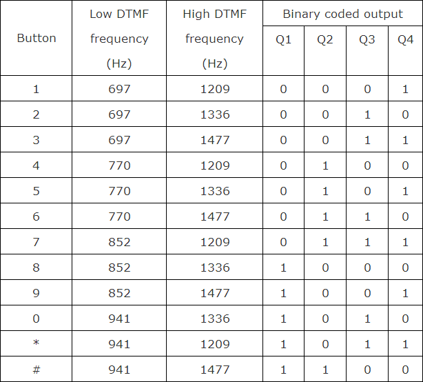
DTMF based robotic vehicle circuit consists of DTMF Decoder IC, Motor Driver IC (L293D or L298N), motors and a simple robot chassis to hold all these components. DTMF decoder IC used is HT9170B (actually a variant called CM8870 is used but the functionality is the same). It has 18 pins. Tone from DTMF encoder is given to the DTMF decoder IC. The decoder IC internally, consists of operational amplifier, whose output is given to pre filters to separate low and high frequencies. Then it is passed to code detector circuit and it decodes the incoming tone into 4bits of binary data. This data at the output is directly given to the driver IC to drive the two motors. These motors rotate according to the decoded output. The following image shows the binary decoded output corresponding to the key pressed on the keypad.
If the button pressed from mobile is ‘8’, it gives a decoded output of ‘1000’ (in the order of Q1, Q2, Q3 and Q4). Thus motor connected to the first two pins (OUT1 and OUT2) will rotate and the second motor stays off. So, the robot moves in one direction either to left or right. If the robot is to rotate forward or backward then the binary value should be either ‘0101’ or ‘1010’. These values indicate that two motors rotates in the same direction i.e. either forward or backward. The above table gives the low frequency, high frequency and binary output value of each button pressed in the keypad.
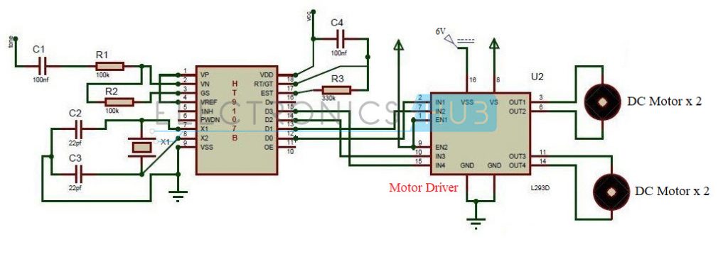
Circuit Diagram of DTMF Controlled Robot without Microcontroller
Circuit Components
DTMF Decoder IC (HT9170B or CM8870) Motor Driver IC (L293D or L298N) Motors Resistors – 100KΩ x 2, 330KΩ Capacitors – 100nF x 2, 22pF x 2 Crystal – 3.58MHz Robot Chassis Batteries
NOTE
As mentioned earlier, the DTMF Decoder IC used here is CM8870. But the circuit diagram mentiones the DTMF Decoder IC as HT9170B. Since the pins are same, there won’t be any problem. But please refer to the datasheet. Also, the circuit diagram mentions the Motor Driver as L293D but the motor driver used here is L298N. Please refer the datasheet for pin diagram.
DTMF Controlled Robot Circuit Design
The main components of the circuit are DTMF decoder IC, motor driver IC and motors. The decoder IC used here is CM8870 IC. The second pin of decoder IC is an inverting pin of the operational amplifier. Tone is applied to the IC through a series of capacitor and resistor. The output of the Op Amp is feed back through GS pin of the IC. An external crystal is connected to the 7th and 8th pins of the IC. Motor driver IC used is L298N. It has 15 pins. If you are using a Module, then connect the Outputs from the decoder IC to IN1, IN2, IN3 and IN4. The motors are connected to OUT1, OUT2, and OUT3, OUT4.
How to operate DTMF based Robotic Vehicle?
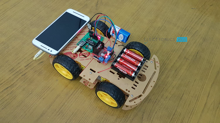
Arrange the robot mechanically i.e. connect the wheels to the motors, place the circuit on the robot with a mobile fixed to it. Now press ‘5’ from your mobile, robot starts moving forward. Now press ‘0’ from your mobile, robot starts moving backward. Now press ‘2’ to rotate the robot in left direction. Now press ‘8’ to rotate the robot in right direction.
DTMF Controlled Robotic Vehicle Circuit Applications
DTMF robot with slight modifications can be used in industrial applications. DTMF robot with human detector sensor can be used at the time of disasters like earth quake to detect the human under buildings. DTMF robot with camera can be used in surveillance systems.
Limitations of DTMF Controlled Robotic Vehicle
DTMF robot may not work properly if it is operated with another mobile when there is no signal. Mobiles with particular jacks are only used.
I really appreciate your project and thank you very for the detailed explanation. It helped me a lot. However, I am currently working on DTMF Controlled Robot ‘WITH’ Microcontroller. So, If you have a similar analysis, could you please share? Also, I am looking for applications of dtmf based moving robot for industrial monitoring (using microcontroller). Any info regarding the subject would be of great help. Even if anybody else has any info, please mail me. Thanks in advance! My email id: haritha.padala124@gmail.com I’m trying to simulate this project on Proteus but can’t find the DTMF decoder HT9170B or anything similar. Could you please tell me how you did it? thanks in advance Comment * Name * Email * Website
Δ
![]()
![]()
![]()


![]()
![]()

