Bridge Rectifier:
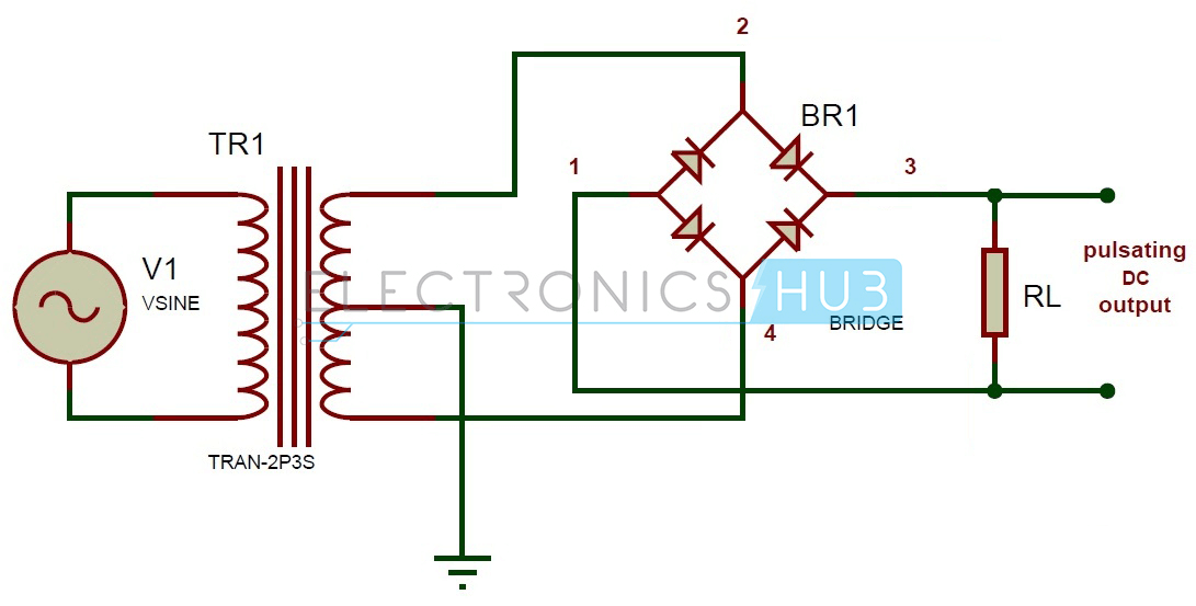
In bridge rectifier four diodes are used. These are connected as shown in the circuit diagram. The four diodes are connected in the form of a bridge to the transformer and the load as shown.
Working of Bridge Rectifier:
The working of a bridge rectifier is simple. The circuit diagram of bridge rectifier is given above. The secondary winding of the transformer is connected to the two diametrically opposite points of the bridge at points 1 and 3. Assume that a load is connected at the output. The load RLoad is connected to bridge through points 2 and 4. During first half cycle of the AC input, the upper portion of the transformer secondary winding is positive with respect to the lower portion. Thus during the first half cycle diodes D1 and D4 are forward biased. Current flows through path 1-2, enter into the load RL. It returns back flowing through path 4-3. During this half input cycle, the diodes D2 and D3 are reverse biased. Hence there is no current flow through the path 2-3 and 1-4. During the next cycle lower portion of the transformer is positive with respect to the upper portion. Hence during this cycle diodes D2 and D3 are forward biased. Current flows through the path 3-2 and flows back through the path 4-1.The diodes D1 and D4 are reverse biased. So there is no current flow through the path 1-2 and 3-4.Thus negative cycle is rectified and it appears across the load. Peak Inverse Voltage (PIV) of a bridge rectifier = Maximum of Secondary Voltage
Bridge Rectifier Circuit Analysis:
In the bridge rectifier circuit, among four diodes two diodes conduct during one half cycle. Thus forward resistance becomes double that is 2RF.
Peak Current:
Instantaneous value of the applied voltage to the rectifier is given as Vs = Vsmax sin wt Let us assume that the diode has a forward resistance of RF ohms and a reverse resistance is equal to infinity, thus current flowing through the load RL is given as
i1 = Imax Sin wt and i2 = 0 during the first half cycle and i1 = 0 and i2 = Imax sin wt during second half cycle
The total current flowing through the load resistance RL, the sum of currents i1 and i2 is given as i = i1 + i2 = Imax sin wt for the complete cycle. The peak value of current flowing through the load RL is given as Imax = Vsmax / (2RF + RL)
Output Current:
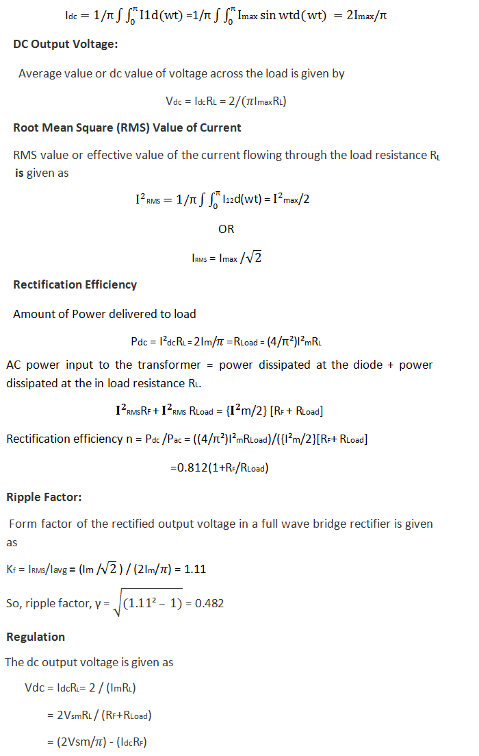
The current flowing is the same through the load RL in the two halves of the ac cycle. Magnitude of the dc current Idc which is equal to the average value of ac current is obtained by integrating the current i1 between 0 and π or current i2 between π and 2π.
A center tap rectifier is difficult one to implement because of the special transformer called center taped is involved. A center tapped transformer is expensive. The main difference between center tap and bridge rectifier is in the number of diodes involved in circuit. A center tap full wave rectifier has only 2 diodes where as a bridge rectifier has 4 diodes. But diodes being cheaper than a center tap transformer, a bridge rectifier are much preferred in a DC power supply. Vsmax is the maximum voltage across the transformer secondary winding whereas in a centre tap rectifier Vsmax represents that maximum voltage across each half of the secondary winding.
Bridge Rectifier Applications:
Because of their low cost compared to center tapped they are widely used in power supply circuit. This can be used to detect the amplitude of modulated radio signal. Bridge rectifiers can be used to supply polarized voltage in welding.
For more information about full wave rectifiers, read the post: Working of Full Wave Rectifier. This circuit would instantly blow the diodes, as the moment there is a differential above 1.4v on 1 and 3, the bottom and top diodes (as series diodes) would switch on and provide a dead short between the transformer secondaries. Comment * Name * Email * Website
Δ
![]()
![]()
![]()
![]()
![]()

