Power is defined as the work performed in a specific time or simply a rate of doing work. Electric power is defined as the electric work done or electric energy dissipated per unit time. It is measured in Joules per second, i.e., watts. The power can be a DC quantity or AC quantity depending on the nature of the power supply. In case of DC circuits, electric power is the product of voltage times the current. The following are the power equations in DC circuits. Pdc = V × I watts = I2 × R = V2 / R In case of AC circuits, electric power includes power factor along with the product of voltage and current. In DC circuits, voltage and currents are in phase and hence power is the product of voltage and current. But, in AC circuits, there exist a phase difference between voltage and current and also their instantaneous values vary from time to time. Therefore, the instantaneous value of power (which is the product of instantaneous voltage and instantaneous current) is not very important in AC circuit. The average power is calculated in AC circuits and it is a very useful quantity. Due to the instantaneous fluctuation of the power, it can be negative or positive. The positive sign indicates the consumption of power by the load while negative sign indicates the returning the power to the source from the load. Most common concentrating term is the dissipated average power from the load, Pavg. The average electric power in a single phase AC circuit is given as Pavg = V × I × cos ϕ watts In the above equation, cos ϕ is the power factor of the circuit and ϕ is the phase angle difference between voltage and current of that circuit. V and I are the RMS values of voltage and current. In case of three-phase AC circuits the electric power is expressed as Pac = √3 × VL × IL × cos ϕ watts Where VL and IL are the line voltage and line current respectively.
Power Measurement in DC Circuits
Method – 1
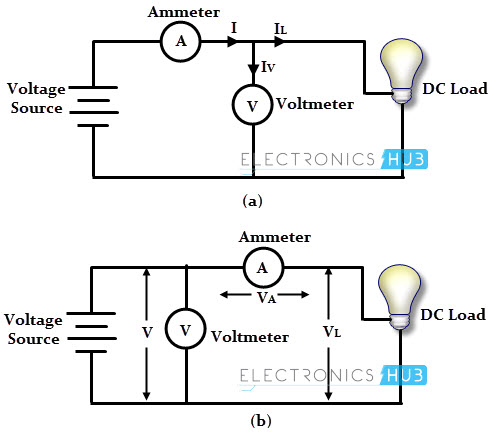
As said earlier, the DC power is the product of voltage across the load and current through the load. Therefore, the power can be determined by using voltmeter and ammeter , by connecting them in any one of the given arrangements below and hence the power can be calculated by the product of these parameters.
In figure (a), the ammeter measures the total current through the circuit and this current is the sum of current through the load and current through voltmeter. So the measurement of power includes the power absorption by the meter. This is avoided in arrangement (b), but the voltmeter measures the voltage drop across the ammeter in addition to voltage across the load and hence the error in the measurement. These errors are called as insertion errors. However, these errors can be neglected when Iv is compared with I and Va compared with V. so the measured power will coincide with true power. Since the voltmeter and ammeter are more sensitive than a wattmeter, the measured value is more accurate than that obtained by a wattmeter. Therefore, power can be calculated by the reading obtained by the meters. P = V × I watts
Method – 2
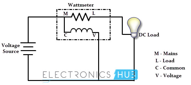
The above method needs two measuring devices and also requires some calculations. It is also possible to measure the power directly by a single meter, called wattmeter. It is an electrodynamic instrument consisting of a pair of fixed coils and a moving coil.
The two fixed coils are called as current coils connected in series with the circuit and are positioned coaxially with space between them. These current coils carry the current proportional to the load current. The current flowing through these coils generates the magnetic field around current coils. The moving coil is called potential coil which is placed between the fixed coils and it carries a pointer that moves over a scale to indicate the power. This potential coil is connected in parallel with the circuit and hence it carries the current proportional to the voltage across the load. The interaction of two currents (or fluxes produced by these currents) produces the torque thereby the pointer moves. This torque is proportional to the product of the current through fixed coils and the current in moving coil. Hence the deflection of pointer (or moving coil) is proportional to the power dissipated into the load. The wattmeter connection for power measurement in a DC circuit is given in the figure below. The wattmeter consists of four terminals namely, Mains (M), Load (L), Common (C) and voltage (V). In this connection, M and L terminals are connected to the either side of load circuit while C and V terminals are connected across the circuit. For a power measurement, M and C terminals must be shorted as shown below.
Nowadays, electronic wattmeters are used for small power measurements and also for the power measurements which are rated at frequencies higher than the electrodynamometer type wattmeter. These are used for high precision accurate measurement applications. Electronic wattmeters can be analog or digital type. Modern digital electronic wattmeter provides thousands of voltage and current samples per second. Also logs the power values in the memory and displays them on a digital display.
Power Measurement in AC Circuits
Most of the AC power measurements rated at frequencies below 400 Hz are carried out using dynamo meter type wattmeter. This measuring instrument indicates directly the average power dissipated by the load. Only one wattmeter is used in case of single phase power measurement while two wattmeters are needed to measure the three phase power. In case unavailability of wattmeters or incorrect measurements by a wattmeter, other methods are used.
Power Measurement in Single AC Circuits
Single phase power can be measured in number ways and common methods of these measurements include
Three voltmeter method Three ammeter method Wattmeter method
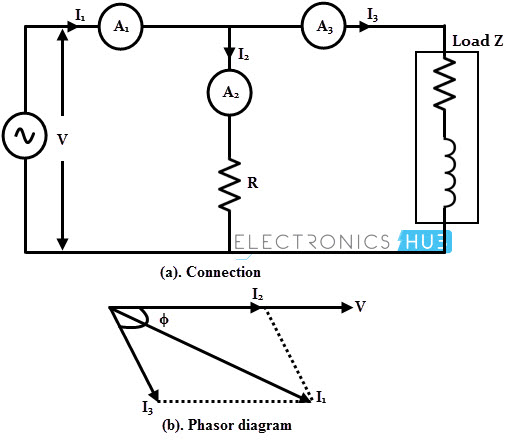
The power in a single phase circuit can be measured using three voltmeters and the connection circuit for this method is shown in figure below. Here the load is inductive, V1, V2 and V3 are voltmeters and R is a purely non-inductive resistance, which is connected in series with the circuit. From the above circuit, the voltage V1, is the vector sum of V2 and V3, i.e., V1 = V2 + V3. In phasor diagram, the current through the circuit, I is taken as a reference phasor and hence V2 will be in phase with I while V3 is leads the current by an angle ϕ (due to inductive circuit). From the phasor diagram, V12 = V22 + V32+ 2 V2 V3 cos ϕ But, V2 = IR V12 = V22 + V32 + 2 (IR) V3 cos ϕ = V22 + V32+ 2 PR since power in the inductive load, P = V3 I cos ϕ Therefore, Power P = (V12 – V22 – V32) / 2R Also, power factor of the circuit, cos ϕ = (V12 – V22 – V32) / (2 V2 V3) This method is not very accurate because small errors in the voltmeter may cause serious error in the measured power. So the accuracy depends on the errors in the voltmeters. Due to the addition of resistance R, supply voltage may be higher than the load voltage and also it is difficult to get non-inductive resistance in practice. The circuit diagram of measuring single phase power with the use of three ammeters is shown below. In this method, a non-inductive resistance R is connected across the inductive load with three ammeters arrangement. The current measured by ammeter-1 is the vector sum of the current taken by the non-inductive resistance and the current through the load.
From the phasor diagram, the current through the non inductive resistance, I2 is in phase with the voltage across the circuit, V. Here, the voltage across the circuit is taken as reference vector. And the current measured by ammeter A3, lags the voltage by angle ϕ. From the phasor diagram, I12 = I22 + I32 + 2 I2 I3 cos ϕ But, I2 = V/R I12 = I22 + I32 + 2 (V/R) I3 cos ϕ Since the power, P = V I3 cos ϕ, I12 = I22 + I32 + (2 P)/R Therefore, power P = (I12 – I22 – I32) R / 2 Also, power factor of the circuit, cos ϕ = (I12 – I22 – I32) / (2 I2 I3) The advantage of this method is that the power determined by this circuit independent of supply frequency and its waveform. As discussed DC power measurement, current coil of the dynamometer type wattmeter carries the load current while the pressure coil carries the current in proportional and in phase with the voltage of the circuit. So the deflection of the meter depends on the currents of these coils and the power factor of the circuit. The connection for single phase power measurement using a dynamo meter type wattmeter is shown in figure below.
In order to measure the power, the load current must pass through the current coil (C.C) and hence it is connected in series with the load whereas the voltage across the load must appear across the pressure coil (P.C.) of the meter and hence it is connected across the load. If the wattmeter gives the power reading in watts, then W = V I cos ϕ
Power Measurement in Three Phase AC Circuits
Electrodynamometer type wattmeters are used for three phase AC power measurements as similar to the single phase AC measurements. Three phase power measurement can be applied for balanced or unbalanced load and whether the load is connected in either star or delta. The balanced load means the magnitudes all of impedances are equal, phase angles of all of them are equal and with same nature either all resistive, or all inductive, or all capacitive. Otherwise the loads are said to be unbalanced. The three-phase power can be measured by following methods.
Three wattmeters method Two wattmeters method One wattmeter method
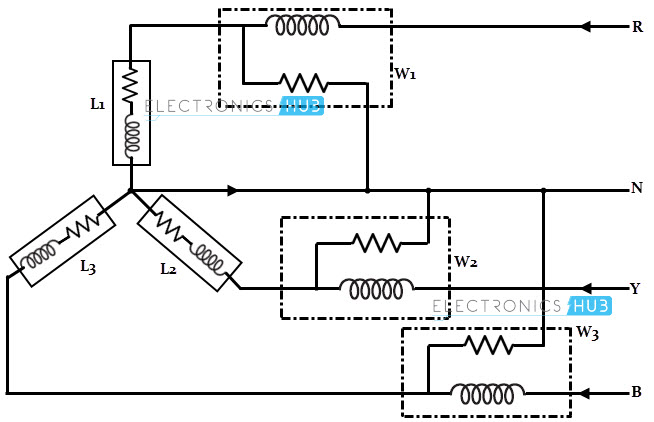
In this method, three wattmeters are connected in each of the three phases whether the load is delta or star connected. The algebraic sum of readings obtained by these three meters gives the total power consumed by the load. The connection diagram for three phase power measurement for star connected load is given below. The current coil of each wattmeter carries the current through that phase while the pressure coil measures the phase voltage of that phase. Thus, each wattmeter measures the single phase power and the algebraic sum of these readings gives the three phase power. In this method, neutral connection is needed for connecting wattmeters. The connection diagram for three phase power measurement for a delta connected load is given below. It is also similar to the star connected load, where the three phase power is obtained by algebraic sum of thee individual wattmeter readings. However, this method is not feasible because we have to break the load circuit to connect wattmeters.
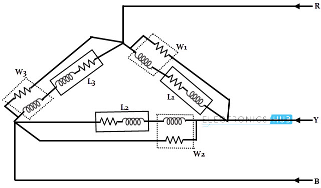
It is not necessary to use three wattmeters for three phase power measurement, but two wattmeters are enough for the measurement. The two wattmeters method of measuring power in three phase circuit is shown in below for star and delta connected loads. In this method, the current coils of wattmeters are inserted in any two lines and their potential coils are connected to the third line. The sum of instantaneous powers measured by these two wattmeters gives the instantaneous power absorbed all the three loads. Before considering the voltage across and current through each wattmeter, it should be noted that the direction of voltage through the circuit as same as that taken for the current when taking out the readings from wattmeters.
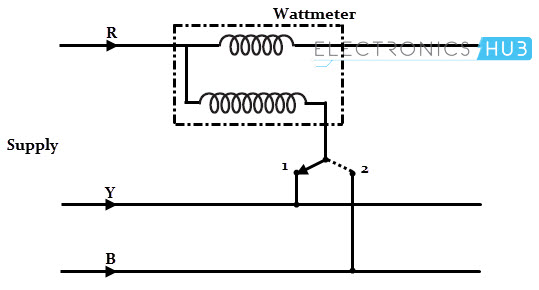
By considering the star connected load (although the following discussion can be applied to delta load by replacing it by an equivalent start load), Instantaneous current through wattmeter-1, I1 = IR Instantaneous voltage across wattmeter-1, V1 = VRB = VR – VB Instantaneous power measured by wattmeter-1, P1 = IR (VR – VB) Instantaneous current through wattmeter-2, I2 = IY Instantaneous voltage across wattmeter-2, V2 = VRB = VY – VB Instantaneous power measured by wattmeter-2, P2 = IY (VY – VB) Therefore, W1 + W2 or P1 + P2 = IR (VR – VB) + IY (VY – VB) = IR VR + IY VY –VB (IR + IY) Since IR + IY + IB = 0 (according to Kirchhoff’s law), then IR + IY = –IB Therefore, W1 + W2 = IR VR + IY VY +VB IB = P1 + P2 + P3 Where P1 is the power consumed by the load L1, P2 is the power absorbed by L2 and P3 is by L3. So the power measured by the two wattmeters is the total power absorbed by the load. This is true whether the load is balanced or unbalanced. The above calculations are based on instantaneous power, however the wattmeters read the average power in the circuit. Total power, P = W1 + W2 = √3 VL IL cos ϕ In this method, a single wattmeter is used to measure the three phase power by obtaining two readings as in case of two-wattmeter method. In this method, two wattmeters are replaced by a single wattmeter and it is possible to take two readings without breaking the circuit. In this, current coil is connected in one line and the pressure coil is connected between this line and other two lines alternately. The sum of readings obtained during switch 1 and switch2 position gives the total power absorbed by the load. This method is used only when the load is balanced load and hence not universally used. Most commonly two wattmeter method is used. Comment * Name * Email * Website
Δ
![]()
![]()
![]()


![]()
![]()

