However to display the characters and numbers (in order to produce the decimal readout), seven-segment displays are most commonly used. Mostly these displays are driven by the output stages of digital ICs (to which the visual indication of the output stages has to be performed) such as latches and decade counters, etc. But these outputs are in the form of 4-bit binary coded decimal (BCD), and not suitable for directly driving the seven-segment displays. A display decoder is used to convert a BCD or a binary code into a 7 segment code. It generally has 4 input lines and 7 output lines. Here we design a simple display decoder circuit using logic gates. Even though commercial BCD to 7 segment decoders are available, designing a display decoder using logic gates may prove to be beneficial from economical as well as knowledge point of view. Back to top
Principle of Display Decoder Circuit
The basic idea involves driving a common cathode 7-segment LED display using combinational logic circuit. The logic circuit is designed with 4 inputs and 7 outputs, each representing an input to the display IC. Using Karnough’s map, logic circuitry for each input to the display is designed.
Theory Behind the Circuit:
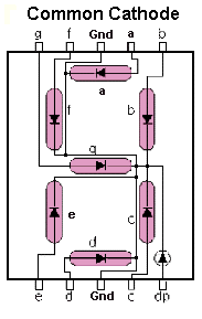
The first and foremost aspect of this circuit is decoder. A decoder is a combinational circuit which is used to convert a binary or BCD (Binary Coded Decimal) number to the corresponding decimal number . It can be a simple binary to decimal decoder or a BCD to 7 segment decoder. Another relevant section is the combinational logic circuitry. A combinational logic circuit is a system of logic gates consisting of only outputs and inputs. The output of a combinational logic circuit depends only on the present state of the inputs and nothing else. Best examples of such circuits are Encoders and Decoders, Multiplexers and De-multiplexers, Adders, Subtractors etc. To understand the design and operation of these logic circuits, one needs to have a good knowledge about Boolean algebra and logic gates. For example few basic Boolean algebra rules to be followed are the complementary law, associative law, De-Morgan’s law etc. A 7 segment LED display consists of an arrangement of 8 LEDs such that either all the anodes are common or cathodes are common. A common cathode 7 segment display consists of 8 pins – 7 input pins labeled from ‘a’ to ‘g’ and 8th pin as common ground pin. Back to top
7 Segment Display Decoder Circuit Design
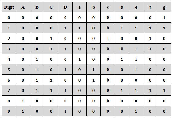
Step 1: The first step of the design involves analysis of the common cathode 7-segment display. A 7-segment display consists of an arrangement of LEDs in an ‘H’ form. A truth table is constructed with the combination of inputs for each decimal number. For example, decimal number 1 would command a combination of b and c (refer the diagram given below). Image Resource Link: www.thelearningpit.com Step 2: The second step involves constructing the truth table listing the 7 display input signals, decimal number and corresponding 4 digit binary numbers. The truth table for the decoder design depends on the type of 7-segment display. As we mentioned above that for a common cathode seven-segment display, the output of decoder or segment driver must be active high in order to glow the segment. The figure below shows the truth table of a BCD to seven-segment decoder with common cathode display. In the truth table , there are 7 different output columns corresponding to each of the 7 segments. Suppose the column for segment a shows the different combinations for which it is to be illuminated. So ‘a’ is active for the digits 0, 2, 3, 5, 6, 7, 8 and 9.
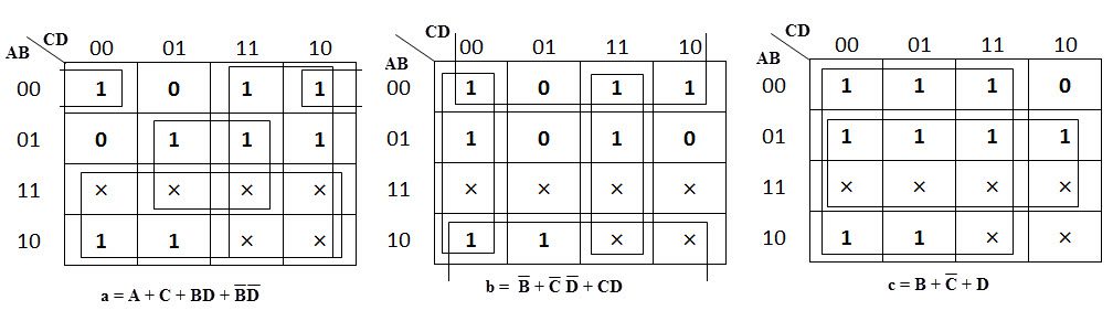
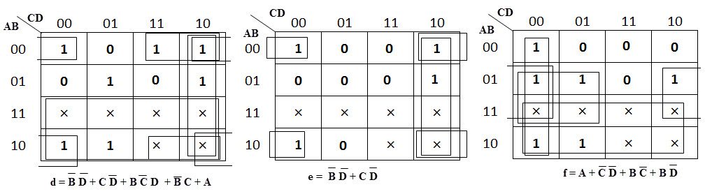
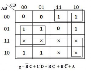
From the above truth table, the Boolean expressions of each output functions can be written as a = F1 (A, B, C, D) = ∑m (0, 2, 3, 5, 7, 8, 9) b = F2 (A, B, C, D) = ∑m (0, 1, 2, 3, 4, 7, 8, 9) c = F3 (A, B, C, D) = ∑m (0, 1, 3, 4, 5, 6, 7, 8, 9) d = F4 (A, B, C, D) = ∑m (0, 2, 3, 5, 6, 8) e = F5 (A, B, C, D) = ∑m (0, 2, 6, 8) f = F6 (A, B, C, D) = ∑m (0, 4, 5, 6, 8, 9) g = F7 (A, B, C, D) = ∑m (2, 3, 4, 5, 6, 8, 9) Step 3: The third step involves constructing the Karnough’s map for each output term and then simplifying them to obtain a logic combination of inputs for each output. The below figures shows the k-map simplification for the common cathode seven-segment decoder in order to design the combinational circuit.
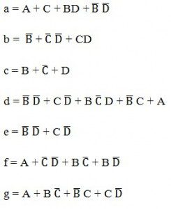
From the above simplification, we get the output values as
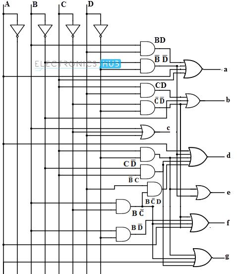
Step 4: The final step involves drawing a combinational logic circuit for each output signal. Once the task was accomplished, a combinational logic circuit can be drawn using 4 inputs (A,B,C,D)and a 7- segment display (a,b,c,d,e,f,g) as output.
Back to top
Display Decoder Circuit Operation
The circuit operation can be understood through the truth table itself. When all the inputs are connected to low logic , the output of the combinational logic circuit would be so as to drive all the output LEDs except ‘g’ to conduction. Thus the number 0 will be displayed. Similar operation would take place for all other combinations of the input switches. Practically BCD to 7 segment decoders are available in form of integrated circuits such as 74LS47. Apart from regular 4 input pins and 7 output pins, it consists of a lamping test pin used for segment testing, ripple blanking input pin used to blank off zeros in multiple display systems, ripple blanking output pin used for cascading purposes and a blanking input pin.
Back to top
Applications of Display Decoder Circuit
[Also Read: How To Make an Adjustable Timer ] Back to top
Limitations of Display Decoder Circuit
Back to top In common anode, the anodes are connected and power is applied. Inputs to activate the segments are a logical 0 (ground) The Truth Table listed above is for a common anode, not a common cathode. To get the Truth Table for a common cathode, flip all the ones and zeros for outputs a-g. Comment * Name * Email * Website
Δ
![]()
![]()
![]()
![]()
![]()

