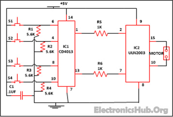
Curtain Opener and Closer Circuit Diagram:
Components used in this Circuit:
IC IC1 (CD4013) IC2 (ULN2003) Resistor R1-R4 (5.6k) R6, R5 (1K) C1 (. 1uf) Stepper Motor
Description:
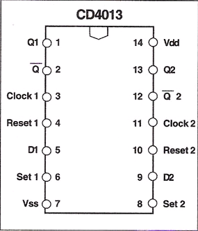
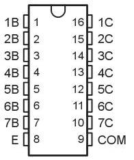
This circuit is made up of two ICs named CD4013 and ULN2003 with few more easily available components. CD4013 IC contains two self-governing D type flip flop on a single chip which exists in one of two states that is 0 or 1 and can store information. Each module is further capable of group of pin outs assigned as data, set, reset, clock input and a couple complementary output Q and .
How D Type Flip Flop Works:
D type flip flop has one input referred to as D input or data input. The truth table of D type flip flop is shown below: This is equivalent to saying that input data appear at the output, at the end of the clock pulse. Thus the transfer of data from input to output is delayed and hence delay (D) flip flop. That’s why it is used as a delay device or latch to store 1 bit binary information. In this clock (CK) input line controls the flip flop which is used to determine whether the input data is recognized or ignored. The input is normally a clock signal. If the clock input is binary high means logic 1 the data on the D line is stored in the flip flop. As long as clock line is high the normal output will simply follow or track the D input. If the CK line is low or it is binary 0 the D input line is recognized. Means the bit store in the flip flop previously retained. The D line can do anything. It will ignore if CK is low. CD 4013 comes in 14 pin dual inline package. Before understanding the working of circuit diagram first have a look at its pin layout. And ULN2003 is basically a Darlington array of high voltage as well as of high current every ULN2003 IC comprise seven unlock collector Darlington couples along with common emitter. ULN2003 is furthermore commonly used in a large variety of loads with the assist of relay drivers or may be employed to drive a stepper motor. ULN2003 works with 5V TTL and CMOS logic devices. Each channel or else Darlington couple in ULN2003 is marked at 500mA and be able to resist peak current of 600mA.Below pin diagram of IC ULN2003 is shown: Working on this circuit is very easy to understand. Assemble the circuit properly and cross check the connection. In this circuit we are utilizing both the flip. If you want to open the curtain just press switch S1 for some time. This will supply the voltage to pin 6 of IC1 (which is set pin) as one end of the switch is connected with power supply and when pin 6 goes high it will provide you the highest output at pin 1 of IC1 that is at Q output. Which in turn makes the pin 2 of IC2 also high and the geared motor connected at the output start revolving in the close wise direction to open the curtain. Now when the curtain is open properly or you want to stop the motor in between just press the switch S2 connected at pin 4 of IC1 which is reset pin and this is used to off or stop the stepper motor when the curtain in fully open or you want to stop in between. A similar occurrence will happen if you want to close the curtain. Just press switch S3 for some time connected to pin 8 of IC1 which is also a set pin. Geared motor starts running in anticlockwise direction. Now when the curtain is close or you want to stop in between press the switch S4 to off the stepper motor. Therefore you can now open and close your curtain just by sitting in one place, without moving just by pressing the switch. Are you interested to know more about Flip Flops? Then read the following posts:
SR Flip Flop Design with NAND and NOR Gates JK Flip Flop using CD4027
Comment * Name * Email * Website
Δ
![]()
![]()
![]()


![]()
![]()

