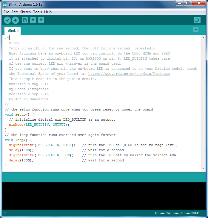
In this tutorial, we will try to understand the Blink program, its components, some syntax and some predefined functions. We will also try to make some changes to the original Blink sketch and see what difference it makes to the output. For this, we need to start the Arduino IDE (with Arduino UNO board already connected to the computer) and open the blink sketch.
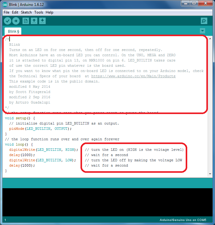
In the sketch shown above, we can see some lines in grey color in the top of the sketch and some colorful lines in the bottom of the sketch. This is because, any Arduino sketch (or as a matter of fact any program irrespective of the programming language) is a combination of some reference line called as comments and the actual code itself. Comments, as the name indicates, is a part of the program that informs yourself or any other going through the program about the way how the program works. They help the source code to be easily understandable by the programmer or user. Generally, comments are ignored by compilers. Hence, do not take up any space while compiling. Comments are again divided in to block comments (also called as multi line comments) and line comments (also called as in line comments). Multiline comments annotate a block or multiple lines in the source code. The grey part in the beginning of the Blink sketch are block comments. They give information like who the developer is, aim of the code, etc.
Multi line comments are usually enclosed between slash (/) – asterisk (*) and asterisk – slash i.e. “/Multiline Comment/”. The other type of comments are line comments. They are used to annotate a single line in the code. Single line comments are generally indicated with a double slash in the beginning. We can see at the end of each line in the code there is a statement with “//”. This is a single line comment. Note: Although comments (either multi line or single line) help the programmer in understanding the code better, they are not mandatory. Even if we delete the comments, the main code won’t be affected.
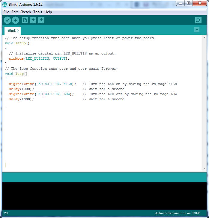
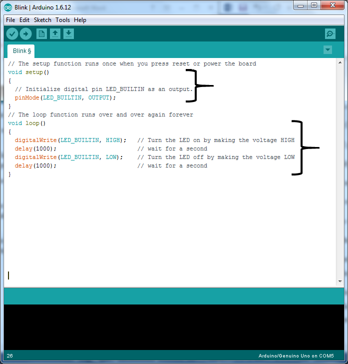
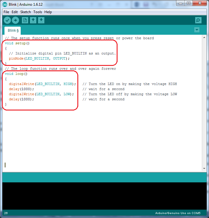
The other part of the sketch is the actual code which is written for Arduino to do a specific task. In Arduino environment, the sketch is divided in to two parts: Setup and loop. The setup () is the first function that is executed or called when program starts. It runs only once when the power is turned on or every time the Arduino is reset. Setup is used to initialize pins, variables, libraries etc. The next function in the Arduino sketch is the loop. As the name indicates, a loop () is a function that runs over and over again i.e. it loops consecutively.
Coming back to the program, the aim is to blink an LED that is connected to the 13th pin of the Arduino UNO. Hence, the first task is to initialize the corresponding pin in the sketch. As we have seen in the introduction tutorial, Arduino UNO has 14 digital pins that can be configured as either input or output. When a pin is configured as input, external data i.e. logic HIGH or LOW is given to Arduino UNO. When a pin is configured as output, Arduino UNO will send either logic LOW or HIGH to that pins. So, in order to initialize a pins as either input or output in Arduino environment, we need to use a function called “pinMode”. The syntax of pinMode function is pinMode (pin no, mode); Here, pin no in the syntax can be any digital I/O pin from 0 to 13 (or any specific identifier) and mode is used to mention whether the pin is input or output. In Arduino UNO, the LED is connected to pin 13 and this has a constant LED_BUILTIN defined in the library. Hence, to initialise the LED pin as an output pin, we have to write the following statement. pinMode (LED_BUILTIN, OUTPUT); As the pinMode function is used to initialise the LED pin, it is written in setup function.
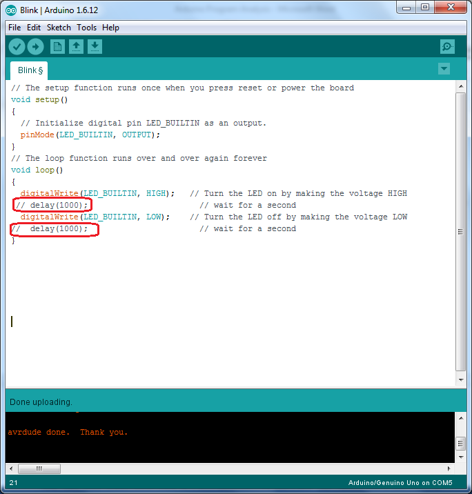
Now that we have successfully initialized the LED pin as output pin, the next step is to turn the LED on or off. The LED will be turned ON when the output of the pin is high and will be turned OFF when the output of the pin is low. In order to drive the output pin as high or low, we need to use another function called “digitalWrite”. The syntax of digitalWrite function is digitalWrite (pin no, value); In the pin no, we have to mention the number or identifier of the pin and in value, we have to mention either HIGH or LOW. Hence, in order to turn ON and OFF the LED we need to write the following statements respectively. digitalWrite (LED_BUILTIN, HIGH); digitalWrite (LED_BUILTIN, LOW); Since the LED must be tuned on and off repeatedly, we need to write these two functions in the loop function. If we observe the sketch, we can see there are two functions called Delay (); placed after each digitalWrite function. Before going to understand this delay function we need to understand a little bit about microcontrollers. Microcontrollers are very fast devices i.e. they execute thousands of instructions in a second. In the above sketch, let us consider we have only the digitalWrite functions without any delay functions in the loop.
In this case, the digitalWrite of HIGH output and digitalWrite of LOW output are executed consecutively at very high speed so that pin is given HIGH and LOW at that speed. Because of this very high speed switching of LED between ON and OFF, we cannot see if the LED is blinking or not and the result will be a dimly glowed LED. In order to slow down this process and properly see the LED blinking, we use the delay function. A Delay function, as the name specifies, is used to delay or pause the execution of the program for a specified time. In Arduino environment, we have two types of delay functions: Delay (); and DelayMicroseconds (); The syntax of both the functions are Delay (time in milli seconds) and DelayMicroseconds (time in micro seconds); (The syntax specifies the functionality of each function). So, coming back to the program, in order to turn ON and OFF the LED at an interval of 1 second (1000 milli seconds), we use the delay function Delay (1000); after each digitalWrite function. To experiment, we can connect an LED (with a current limiting resistor) to any other pin and write the sketch accordingly. Also, we can change delay time and see the rate at which the LED blinks. In the next tutorial, we will continue exploring the Arduino by making some changes to the circuit and also sketch and learn how to write our first program. Comment * Name * Email * Website
Δ
![]()
![]()
![]()
![]()
![]()

