I will discuss about the Analog Joystick Module, what a typical Joystick module consists of (i.e. its components), how the joystick module works and finally how to interface a Joystick with Arduino.
A Brief Note on Analog Joystick Module
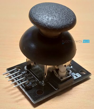
You might have come across Joystick or Analog Stick as a Game Controller Device. A Joystick (sometimes also called as Thumb stick) is an input device and the Analog Stick is a type of Joystick which provides a 2-Dimensional Input. NOTE: For the rest of the project discussion, only the term “Joystick” is used. A typical Joystick module is shown in the following image.
An Analog Joystick usually consists of Potentiometers (two for each axis) and based on the position of these potentiometers, input is given (to a microcontroller, for example). A knob or a protrusion is used to change the position of the potentiometers.
Components of Joystick
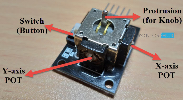
The following image shows the internal components of a typical Analog Joystick. There are two Potentiometers of 10KΩ each and additionally there is a switch which can be activated by pushing the knob down.
The following image shows the internal connections in a Joystick Module. As mentioned earlier, it consists of two 10KΩ Potentiometers, a push button (switch) and connectors (Pins).
Pins of a Joystick
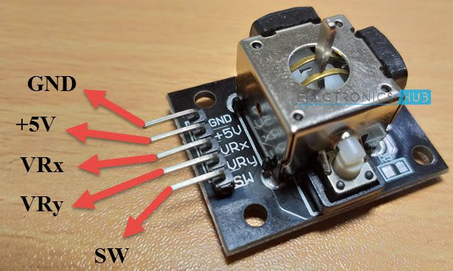
A typical Joystick Module consists of 5 Pin on its board. They are:
VRx VRy SW +5V GND
Here, +5V and GND pins must be connected to, well +5V and GND of a power supply (you can connect them to respective pins on Arduino). The VRx and VRy are the Wiper terminals of the two potentiometers. Finally, SW is one end of a switch, where its other terminal is connected to GND (on the board of the Joystick). The following image shows the pin diagram of the Joystick Module I am using. The orientation of the pins may vary depending on the manufacture but the pins will be the same.
Arduino Joystick Interface
Now that you are familiar with the components and pins of a typical Joystick Module, let me take you through the Arduino Joystick Interface i.e. how to interface a Joystick with Arduino?
Since, the joystick is essentially a combination of two potentiometers (and a Switch, of course), you can easily guess how to interface it with Arduino as you might have already connected a potentiometer with Arduino.
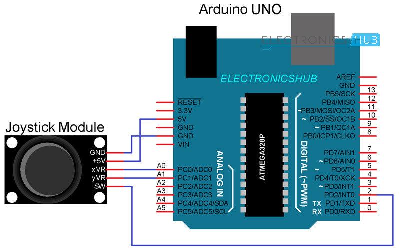
Circuit Diagram
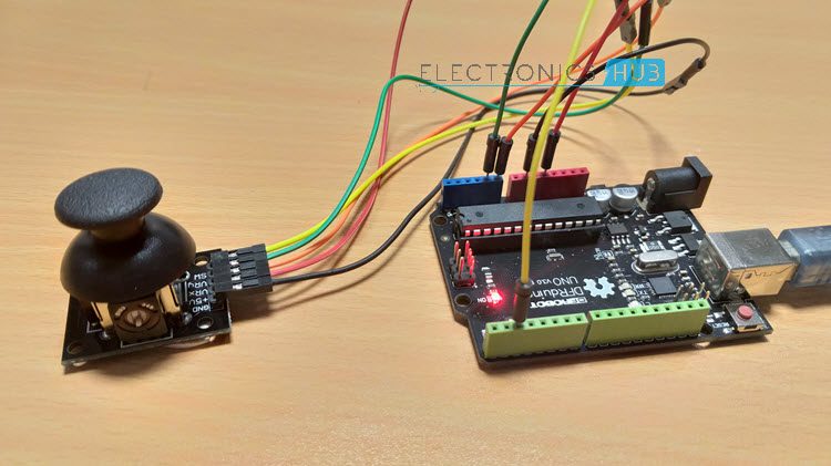
The following image shows a simple connection between Arduino UNO and the Joystick Module.
Code
Circuit Design and Working
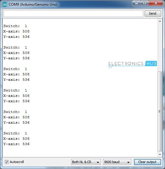
I think the design of the circuit is very clear. Since the VRx and VRy pins are the wiper pins of the Potentiometers, they must be connected to the Analog Input pins of the Arduino UNO (as they give us analog voltages). The switch pin on the other hand, is connected to Digital I/O Pin 2, with internal pull-up (implemented through code). Coming to the working of the circuit, once the connections are made and the code is uploaded to Arduino, open the serial monitor. In that you can see the current values from both the potentiometers as well as the switch being updated on a regular basis (based on the delay).
Since the input is Analog and we are converting it to Digital values, the output of the Joystick on both X-axis and Y-axis will be in the range of 0-1023. The next step in the Arduino Joystick Interface is to collect the values from the Joystick and use them to control a device, like an LED, motor or a servo.
How to Control Servo Motor with Arduino and Joystick?
There is no use in just interfacing a sensor with Arduino. You have to collect the data from the sensor and use to appropriately. In case of a Joystick Module, you get two potentiometers and a switch. Which means, you get two different sources of Analog Inputs and one Digital Input. Using the Analog Inputs i.e. the X and Y movements of the Joystick, you can control different devices like a Servo Motor, for example and with the Digital Input (the Switch), you can control an LED i.e. turn it ON or OFF.
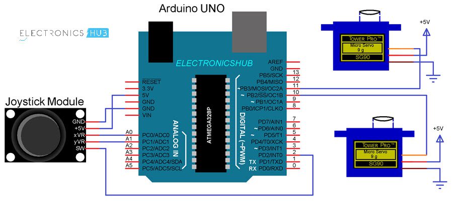
Circuit Diagram
The following circuit diagram shows the necessary connections for controlling two Servo Motors using a Joystick and Arduino.
Code
Circuit Design and Working
The connections with respect to the Joystick Module are the same i.e. +5V and GND to +5V and GND of Arduino, VRx and VRy to A0 and A1 (Analog Inputs 0 and 1) and the SW pin to Digital Pin 2. Coming to the servo motors, their +V (Red) and GND (Brown) wires are connected to +5V and GND (preferably to another 5V Supply with common GND with Arduino). The control wires (Yellow or Orange) of the Servo Motors are connected to Digital I/O Pins 10 and 11. Once the code is uploaded to Arduino, it starts reading the data from the joystick and the default position of both the servos is initialized to 90 (in the range of 0-180).
The idle values from the Joystick are 510 for X-Axis and 530 for Y-Axis in my case. Keeping these in reference, I have written the code such that, when the value from X-axis potentiometer falls below 300, the position of the X Servo is reduced by 5 from its current position and if the value from X-axis potentiometer becomes greater than 700, the position of the X Servo is increased by 5 from its current position. A similar code is implemented even for the Y-Axis potentiometer and the Y Servo. Additionally, the switch of the Joystick is programmed to control the LED connected to Pin 13 of Arduino UNO.
Applications
Joystick can be used in various application like
Controlling DC Motors and Servo Motors Controlling LEDs Remote controlled Cars Robotic Control
Comment * Name * Email * Website
Δ
![]()
![]()
![]()

![]()
![]()

