One of the easiest and cheapest ways to implement wireless communication is using RF Module (Radio Frequency Module). Arduino on the other hand, is a low cost solution for microcontroller applications with open source hardware and software. Arduino can be used in many small to real time applications with simple programming and hardware components. By combining the two objects i.e. wireless communication with Arduino, we can create a wide range of applications like remote controlled cars, wirelessly operated robots, home automation, simple data transfer etc. In this project, we are going to design a system in which two Arduino boards will communicate with each other using RF Module.
Circuit Diagram
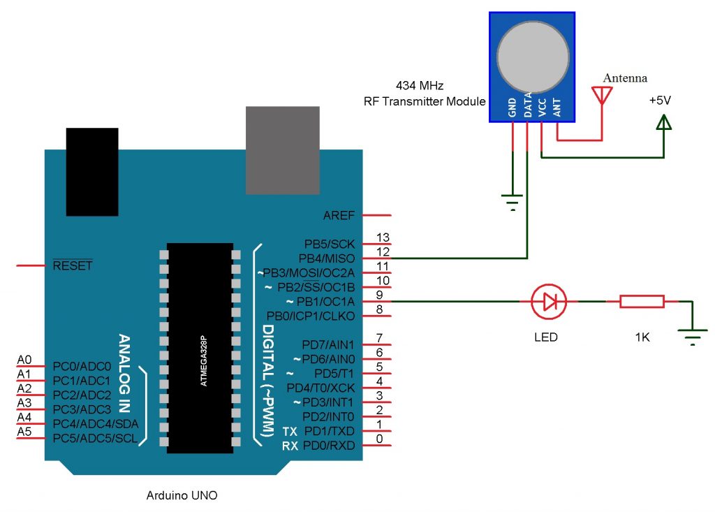
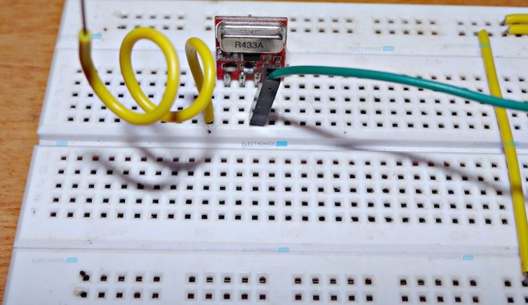
As it is a wireless communication project, the circuit consists of a Transmitter part and a Receiver part. The circuit for the Transmitter part of the project is shown below.
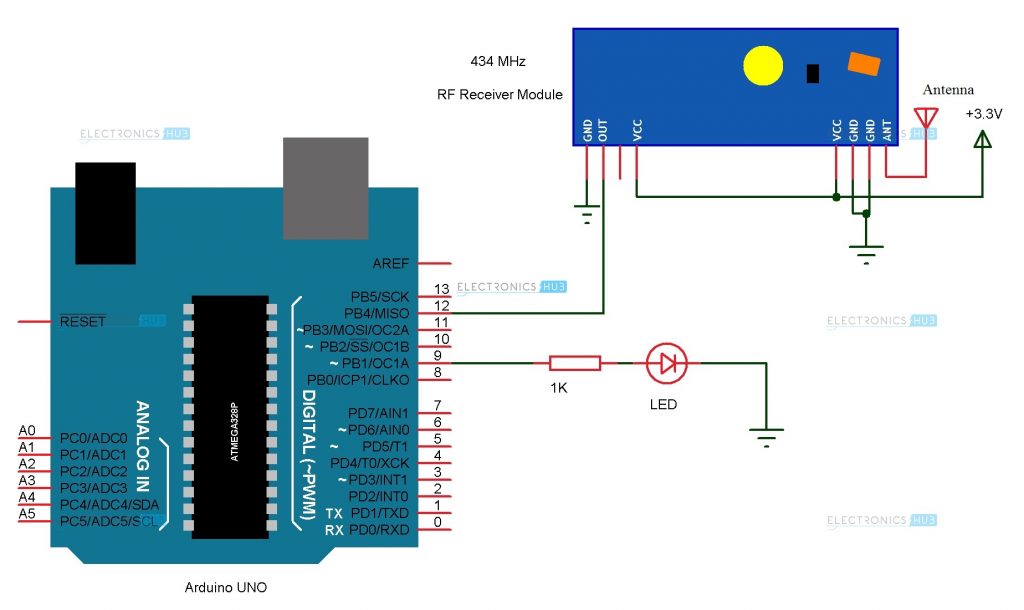
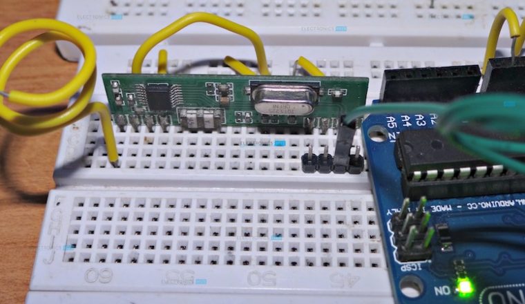
And the circuit for the Receiver part of the project is shown below.
Components Required
Transmitter Part
Arduino UNO (or any other Arduino board) [Buy Here] 434 MHz Transmitter Module (or 315 MHz Module) LED [Buy Here] 1 KΩ Resistor Prototyping board (bread board) Connecting wires Power supply (Adapter or battery)
Receiver Part
Arduino UNO (or any other Arduino board) [Buy Here] 434 MHz Receiver Module (or 315 MHz Module) LED 1 KΩ Resistor Prototyping board (bread board) Connecting wires Power supply (adapter or battery) RF Module
Component Description
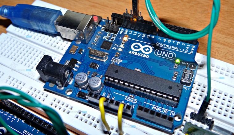
Arduino UNO: Arduino UNO is the low cost, open source, microcontroller board for electronics prototyping. In this project, two Arduino boards will communicate using wireless communication. RF Module: RF Module is a cheap wireless communication module for low cost application. RF Module comprises of a transmitter and a receiver that operate at a radio frequency range. Usually, the frequency at which these modules communicate will be 315 MHz or 434 MHz. Image RF Module Pair In this project, we are using a 434 MHz RF Transmitter – Receiver pair. This module can be used for communication for distances up to 40 meters.
Circuit Design
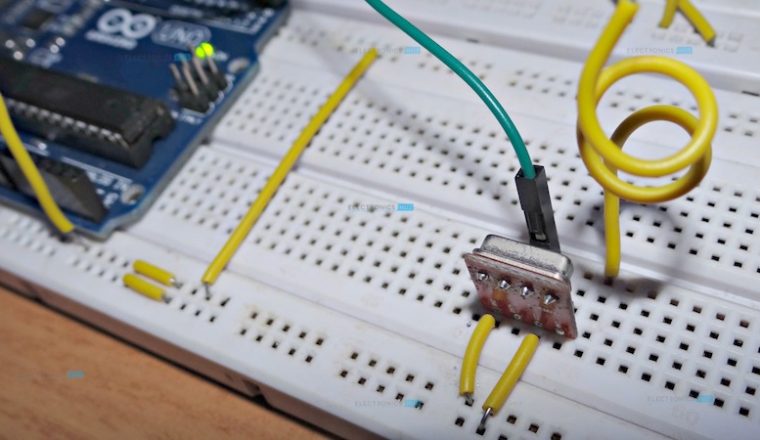
Transmitter Part The transmitter part consists of Arduino UNO and the 434 MHz Transmitter module. An external LED can be used but on board LED would be sufficient. The design of the Transmitter part is as follows. The RF Transmitter Module consists of 4 – pins: VCC, GND, Data and Antenna. VCC and GND pins are connected to 5V and ground respectively. The data pin is connected to any of the digital input / output pin of Arduino. Here, it is connected to Pin 12. The antenna pin must be connected to an antenna which is nothing but a wire wound in the form of a coil. We are using the on board LED for demonstration but an external LED along with current limiting resistor can be used. Receiver Part The receiver part consists of Arduino UNO and the 434 MHz Receiver module. An external LED can be used along with a current limiting resistor but on board LED would be sufficient. The design of the Receiver part is as follows. The RF Receiver Module consists of 4 – pins: VCC, GND, Data and Antenna. VCC and GND pins are connected to 3.3V pin of the Arduino and ground respectively. The data pin is connected to Pin 12 of the Arduino. An antenna similar to the transmitter module is connected to the antenna pin of the 434 MHz Receiver module. The on board LED which is connected to the 13th pin of Arduino is used in the project although an external LED can always be used.
Working Process
In this project, a simple demonstration of RF Communication with the help of Arduino UNO boards is given. The aim of the project is to successfully transmit data between the RF Transmitter – Receiver modules using two Arduino UNO microcontroller boards. The working of the project is explained here. Note: The project can be implemented with or without the help of a special library called “VirtualWire.h”. The project implemented here uses the library. If we want to implement the project without the library, then we need to change the receiver part of the circuit. VirtualWire.h is a special library for Arduino created by Mike McCauley. It is a communication library that allows two Arduino’s to communicate with each other using RF Module i.e. transmitter – receiver pair. This library consists of several functions that are used for configuring the modules, transmission of data by the transmitter module and data reception by the receiver module. In this project, the transmitter simply sends two characters i.e. it sends the character “1” and with a delay of few seconds, it sends the character “0”. Whenever the “1” is sent, the LED on the transmitting side of the project will be turned ON. As this “1” is transmitted via RF communication, the receiver will receive the data “1”. When the receiver receives “1”, the Arduino on the receiver side of the project will turn ON the LED on its side. Similarly, when the data “0” is transmitted by the RF transmitter, the LED on the transmitter side is turned OFF. As a result, the receiver now receives “0” and the LED on the receiver side is also turned OFF. Hence, the receiver is imitating the actions of the transmitter.
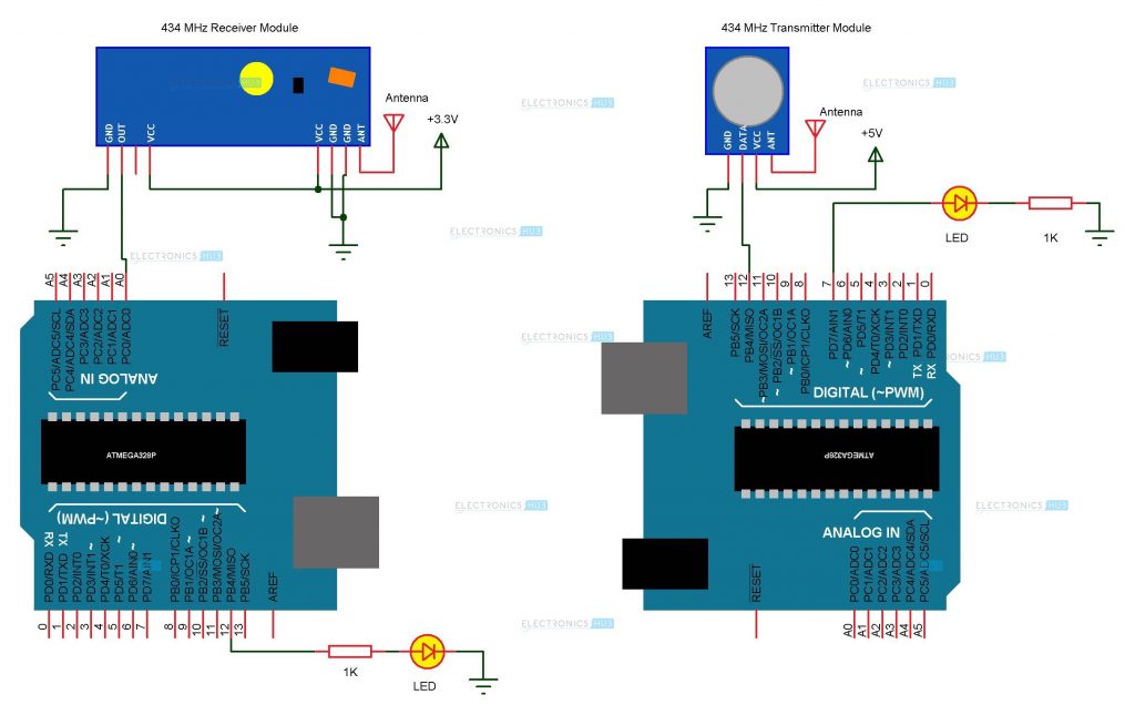
Note: As said earlier, the project uses a special library called VirtualWire. This library used the “Timer” feature of the microcontroller and may affect the timer related properties like PWM for instance. Hence, the following schematic can be used for a similar implementation without use of any library. Image Alternative Schematic The sketch for both the projects i.e. one using the library and the other not using the library are provided.
Applications
As mentioned in the project introduction, wireless communication using RF Modules has a wide range of applications like RC Cars Home Automation Robotics
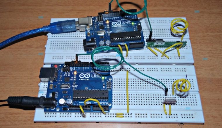
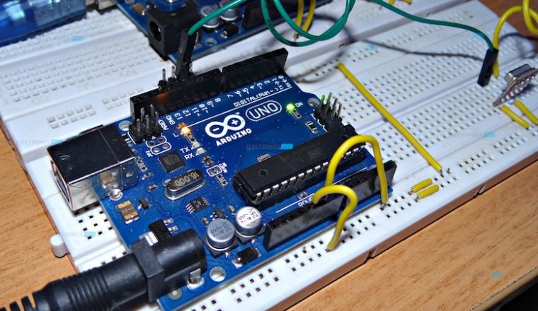
Project Images
Receiver Code with Library
Transmitter Code with Library
Receiver Code without Library
Transmitter Code without Library
Comment * Name * Email * Website
Δ
![]()
![]()
![]()

![]()
![]()

