A 7 segment LED display consists of 7 LEDs arranged in such a way that it can display numbers from 0 to 9. The arrangement of LEDs in the display can be either common anode or common cathode. In this project, a 4 – digit 7 – segment LED display is used to display numbers using Arduino. Either a compact module containing four 7- segment LED displays can be used or four individual 7 – segment displays can be used by multiplexing them.
Circuit Diagram
Components Required
Arduino UNO — 1 [Buy Here] 4 – Digit compact 7 – segment LED display — 1(Or)7 – Segment LED display — 4 BC547 — 4 1KΩ — 4 100Ω — 4
Working of 4 – Digit 7 – Segment LED Display
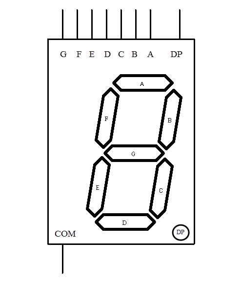
A 7 – Segment LED display, as the name indicates, is an assembly of LED bars, where each bar can be powered individually. Each LED bar is in the form of a hexagon and the overall arrangement will be in the form of ‘8’. The following figure shows a general representation of 7 – segment LED display with dedicated names to each segment.
Each segment can be powered separately to display digits from 0 to 9. The following figure shows the pattern of digits displayed by a 7 – segment LED display.
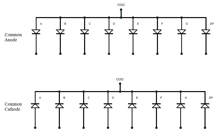
As mentioned earlier, in a 7 – segment display, the LEDs can be arranged in common anode or common cathode mode. The equivalent circuit of a 7 – segment display in common anode and common cathode configuration is shown below.
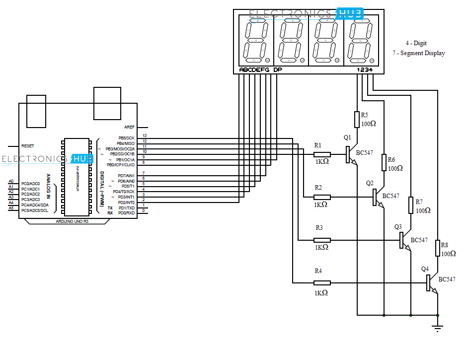
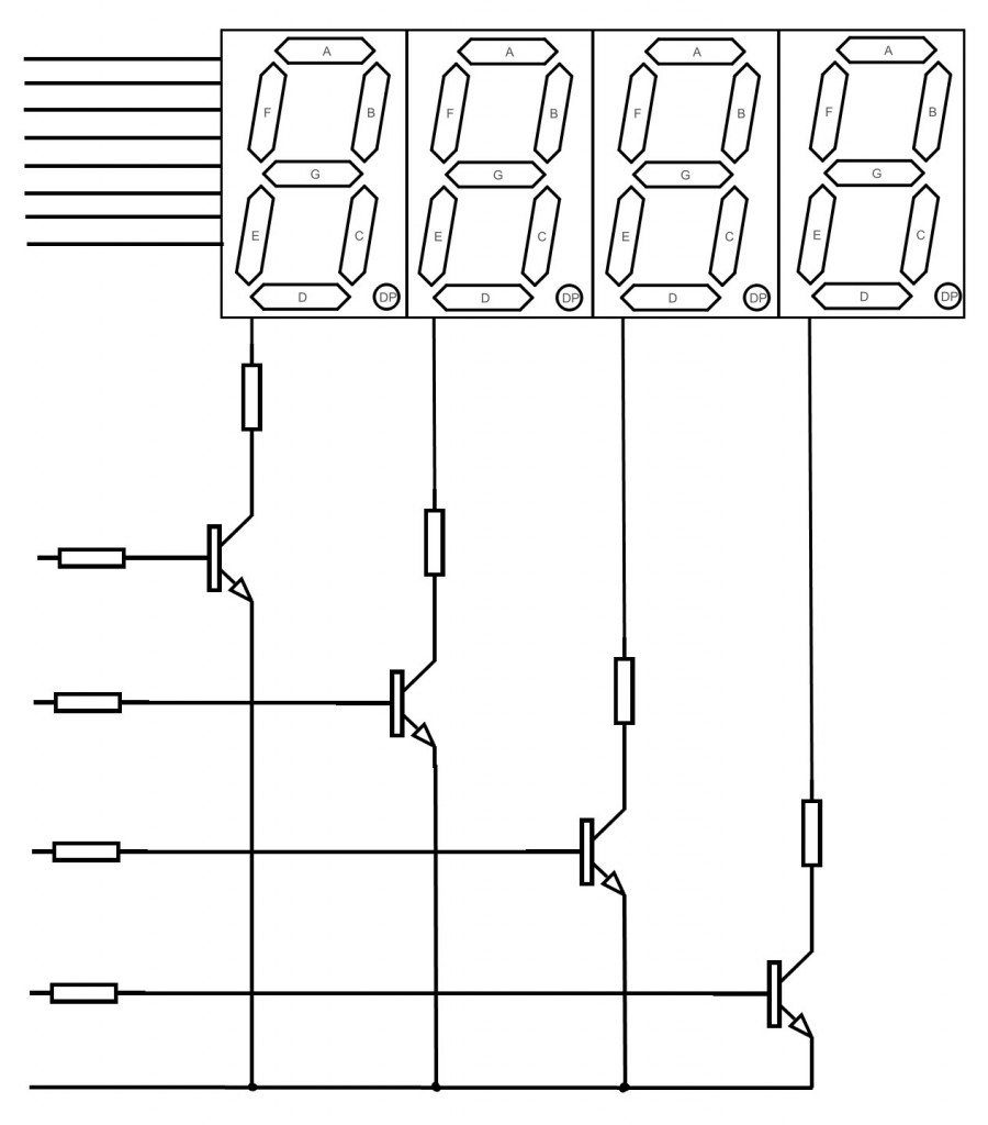
To determine whether the 7 – segment display is common anode or cathode, a small test circuit can be built. The common terminal of the display is connected to a current limiting resistor. The resistor is given positive voltage and any of the segments (A to G) is connected to ground. If the segment glows, then it is common anode display. If the segment doesn’t glow, reverse the polarity of the supply and then it glows. This is a common cathode display. It is important to determine whether the display is of common anode or common cathode type as the code for Arduino (or any microcontroller) will depend on it. In this project, we are using a 4 – digit 7 – segment LED display. We can use a compact 4 – digit module or use four individual 7 – segment displays and multiplex them to make a 4 – digit display. The following figure shows four multiplexed 7 – segment LED displays.
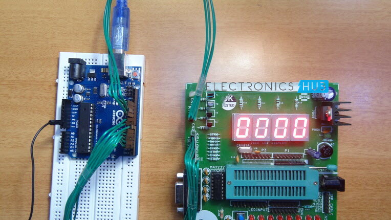
Respective segment pins (A to G and DP) of all the 7 – segment displays are connected with each other. Hence, only 8 pins will be sufficient to control all the eight segments of all four displays. These eight pins are connected to eight pins of Arduino. We assume that the selected 7 – segment module is of common cathode type. The four common pins from four displays are connected to collector terminals of four different transistors through current limiting resistors. The emitter terminals of four transistors are connected to ground. The four base terminal of the four transistors are connected to four pins of Arduino through current limiting resistors. All the connections are shown in the circuit diagram. The aim of this project is to demonstrate the working of a 4 – digit 7 – segment LED display using Arduino by implementing a simple counter. The circuit diagram and written code are developed for common cathode type 7 – segment LED display.
Code
You are free to use above code. Feel free to ask your doubts and questions in below comment. Our technical person love to help you. Please help us . WHATEVER DO IT ASAP THANKS IN ADVANCE Comment * Name * Email * Website
Δ
![]()
![]()
![]()


![]()
![]()

