Project submitted by – Stan Georgian
Overview
In this tutorial, we will create an infrared proximity sensor by looking at basic information without going into too much detail. The operating principle of this sensor will be simple: when an object is in front of the sensor, a blue led will light up. If you want more than just doing the sensor and want to understand how each component goes, then this is the right tutorial. By going through this tutorial, you will learn about: IR LEDs, voltage dividers, op-amp, circuit assembly.
About IR LEDs
We have two LEDs with IR, an emitter and a receiver. When the current passes through the emitter LED, it will emit infrared radiation. This can be seen if you use the camera on an older phone.
The receiver is used in the reverse bias and is used to capture infrared radiation. The cathode (- / shorter leg) of the LED is connected to the source plus. Being in reverse bias, the receiver will allow, in its initial state (without infrared radiation), a small current to pass through it. In our example with 9V power supply, the Led output only shows 0.56V. When infrared radiation falls on the receiver, it will allow a higher current to pass through it. The current depends on the light intensity of the radiation.
Op-amp as comparator
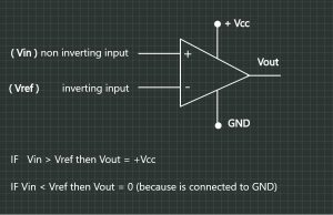
LM358 is an operational amplifier that we will only use as a comparator.
The amplifier has two inputs, plus is the input called non-inverting input and minus the inverting input. We will say that the input with plus (non-inverting) will be a Vin and the minus (inverting) will be a Vref (reference). Besides the two inputs, we have two pins that we connect to the power supply and we will call it Vcc and Ground (GND) respectively. A fifth pin will be the output pin (Vout). The operating mode of the comparator is simple: if Vin > Vref, then Vout = Vcc, and if Vin < Vref, then Vout = 0 because we connect the pin to ground. It is worth mentioning that at the output voltage will be approximately equal to the supply voltage Vout ~ Vcc. Given these things, we will connect the IR Receiver output to the non-inverse input (plus). Initially we said we will have about 0.56V out of the Led when it does not capture infrared radiation. So, we have to initially give a Vref higher than the 0.56V voltage. Here, we will use the potentiometer to set a value higher than 0.56V to pin Vref. In this case in state 0 we have Vin < Vref and Vout = 0, so the led will be off. When the receiver will capture the radiation, it will allow a higher current to pass, a current that will overtake Vref and we will have Vin> Vref and Vout = Vcc, about 9V.
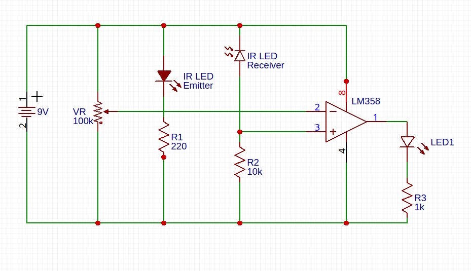
Sensor Schematic
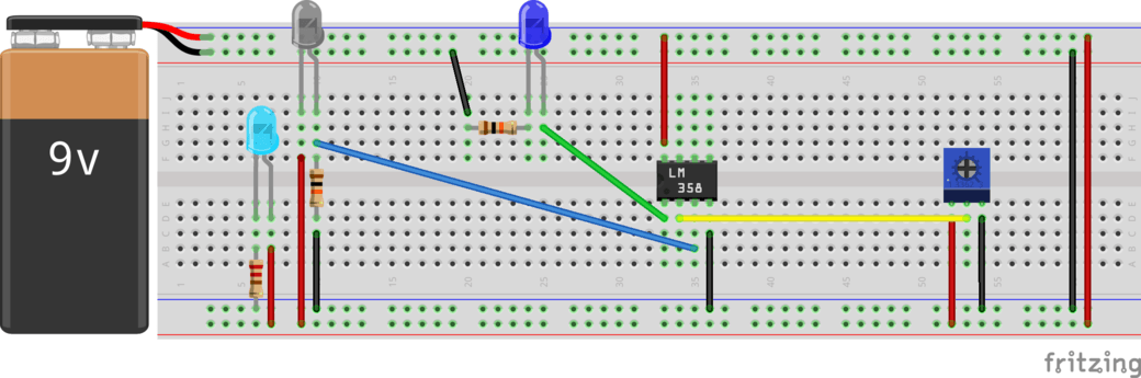
9V Power Supply
The 9V battery will connect as follows: the red and black wire will be placed on a column, and then we will connect columns between them. It is not obligatory to do this in this way, but I preferred to make the circuit easier to view. When we do the rest of the circuit, we will not leave the battery connected.
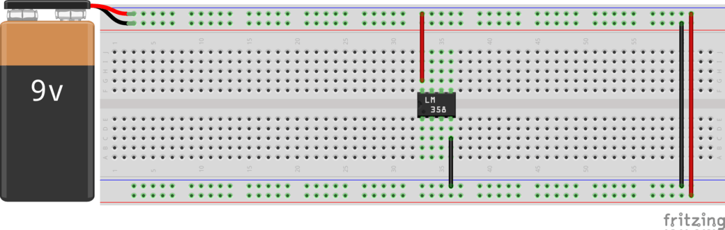
Op-amp
Initially we put the amplifier in the middle of the breadboard so the pins are separated. And we’ll connect to pin 8 to power supply and pin 4 to ground.
Potentiometer
We will put the potentiometer further away from the rest of the circuit so that we can easily adjust the distance. It does not necessarily have to be placed in the middle because pins will not come in the same way anyway. We will connect the pins of the potentiometer as follows.
IR Emitter
We will connect the infrared emitter in series with 220 Ω resistor as follows: the longer LED (cathode) to the plus, and the shorter leg in the same row with resistance and the resistance to ground.
IR Receiver
The next one is the receiver. We will connect it in reverse bias mode and in parallel with the emitter and as close as possible to it. The shorter leg will be connected to plus and the longer leg in series with the 10k ohm resistance and the resistance to the ground.
We will use the receiver and resistance of 10k ohms to make a voltage divider. The schematic for such a circuit looks like this and the following formula applies (see picture). Where at Vin is 9V, R1 is the internal resistance of the infrared led and R2 is the resistance of 10k ohm.
Following the formula, we place the LED before the resistance. In phase 0 when the receiver does not capture infrared radiation, it has a very high internal resistance and the output voltage (Vout) will be small. And when it picks up the radiation, its internal resistance will be very low and the Vout will get a higher. Connect the voltage divider to pin 3 the comparator.
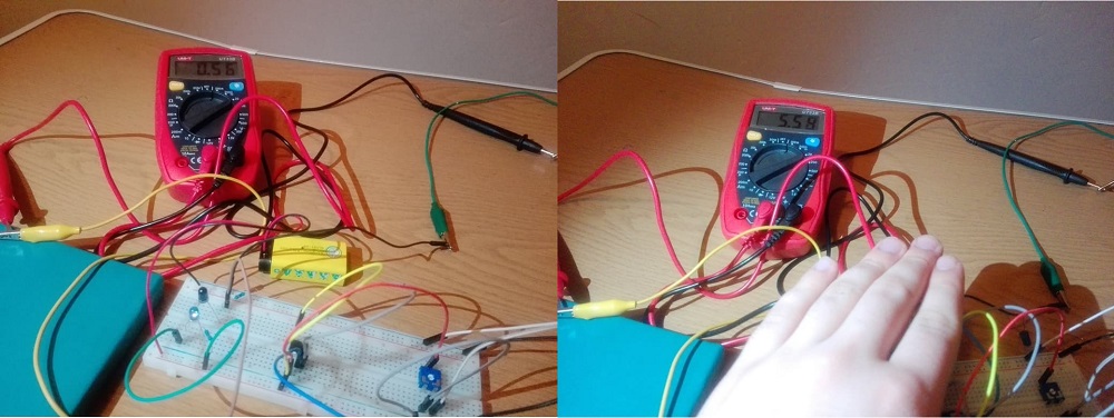
Make use of multimeter
Here comes the multimeter that we will use to measure the voltage coming out of the voltage divider that will be for us Vin in comparator and the voltage coming out of the potentiometer that will be for us Vref in the comparator. We will adjust the potentiometer so Vref will initially be larger than Vin.
Check the circuit
If we get here, it’s time to check our proximity sensor with the multimeter. We connect the battery to the circuit and put the multimeter in parallel with the output from the amplifier (pin 1). Initially it will have to show 0 and when we put something above the infrared light it should look something close to 9V.
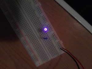
Add an LED
At this point, the sensor is functional and we will add a 1k ohm in series with a blue LED. Considering that the output voltage is quite high I used a blue led because the voltage drop is ~3V. The resistor is connected to pin 1 and in series with the blue led that is grounded. RELATED POST: Operational Amplifier Applications Comment * Name * Email * Website
Δ
![]()
![]()
![]()


![]()
![]()

