Introduction to 8051 Microcontroller Instruction Set
Writing a Program for any Microcontroller consists of giving commands to the Microcontroller in a particular order in which they must be executed in order to perform a specific task. The commands to the Microcontroller are known as a Microcontroller’s Instruction Set. Just as our sentences are made of words, a Microcontroller’s (for that matter, any computer) program is made of Instructions. Instructions written in a program tell the Microcontroller which operation to carry out. An Instruction Set is unique to a family of computers. This tutorial introduces the 8051 Microcontroller Instruction Set also called as the MCS-51 Instruction Set. As the 8051 family of Microcontrollers are 8-bit processors, the 8051 Microcontroller Instruction Set is optimized for 8-bit control applications. As a typical 8-bit processor, the 8051 Microcontroller instructions have 8-bit Opcodes. As a result, the 8051 Microcontroller instruction set can have up to 28 = 256 Instructions.
A Brief Look at 8051 Microcontroller Instructions and Groups
Before going into the details of the 8051 Microcontroller Instruction Set, Types of Instructions and the Addressing Mode, let us take a brief look at the instructions and the instruction groups of the 8051 Microcontroller Instruction Set (the MCS-51 Instruction Set). The following table shows the 8051 Instruction Groups and Instructions in each group. There are 49 Instruction Mnemonics in the 8051 Microcontroller Instruction Set and these 49 Mnemonics are divided into five groups.
8051 Addressing Modes
What is an Addressing Mode?
An Addressing Mode is a way to locate a target Data, which is also called as Operand. The 8051 Family of Microcontrollers allows five types of Addressing Modes for addressing the Operands. They are:
Immediate Addressing Register Addressing Direct Addressing Register – Indirect Addressing Indexed Addressing
Immediate Addressing
In Immediate Addressing mode, the operand, which follows the Opcode, is a constant data of either 8 or 16 bits. The name Immediate Addressing came from the fact that the constant data to be stored in the memory immediately follows the Opcode. The constant value to be stored is specified in the instruction itself rather than taking from a register. The destination register to which the constant data must be copied should be the same size as the operand mentioned in the instruction. Example: MOV A, #030H Here, the Accumulator is loaded with 30 (hexadecimal). The # in the operand indicates that it is a data and not the address of a Register. Immediate Addressing is very fast as the data to be loaded is given in the instruction itself.
Register Addressing
In the 8051 Microcontroller Memory Organization Tutorial, we have seen the organization of RAM and four banks of Working Registers with eight Registers in each bank. In Register Addressing mode, one of the eight registers (R0 – R7) is specified as Operand in the Instruction. It is important to select the appropriate Bank with the help of PSW Register. Let us see a example of Register Addressing assuming that Bank0 is selected. Example: MOV A, R5 Here, the 8-bit content of the Register R5 of Bank0 is moved to the Accumulator.
Direct Addressing
In Direct Addressing Mode, the address of the data is specified as the Operand in the instruction. Using Direct Addressing Mode, we can access any register or on-chip variable. This includes general purpose RAM, SFRs, I/O Ports, Control registers. Example: MOV A, 47H Here, the data in the RAM location 47H is moved to the Accumulator.
Register Indirect Addressing
In the Indirect Addressing Mode or Register Indirect Addressing Mode, the address of the Operand is specified as the content of a Register. This will be clearer with an example. Example: MOV A, @R1 The @ symbol indicates that the addressing mode is indirect. If the contents of R1 is 56H, for example, then the operand is in the internal RAM location 56H. If the contents of the RAM location 56H is 24H, then 24H is moved into accumulator. Only R0 and R1 are allowed in Indirect Addressing Mode. These register in the indirect addressing mode are called as Pointer registers.
Indexed Addressing Mode
With Indexed Addressing Mode, the effective address of the Operand is the sum of a base register and an offset register. The Base Register can be either Data Pointer (DPTR) or Program Counter (PC) while the Offset register is the Accumulator (A). In Indexed Addressing Mode, only MOVC and JMP instructions can be used. Indexed Addressing Mode is useful when retrieving data from look-up tables. Example: MOVC A, @A+DPTR Here, the address for the operand is the sum of contents of DPTR and Accumulator. NOTE: Some authors and textbooks add few other Addressing Modes like Absolute Addressing Mode, Relative Addressing Mode and Long Addressing Mode.
Types of Instructions in 8051 Microcontroller Instruction Set
Before seeing the types of instructions, let us see the structure of the 8051 Microcontroller Instruction. An 8051 Instruction consists of an Opcode (short of Operation – Code) followed by Operand(s) of size Zero Byte, One Byte or Two Bytes. The Op-Code part of the instruction contains the Mnemonic, which specifies the type of operation to be performed. All Mnemonics or the Opcode part of the instruction are of One Byte size. Coming to the Operand part of the instruction, it defines the data being processed by the instructions. The operand can be any of the following:
No Operand Data value I/O Port Memory Location CPU register
There can multiple operands and the format of instruction is as follows: A simple instruction consists of just the opcode. Other instructions may include one or more operands. Instruction can be one-byte instruction, which contains only opcode, or two-byte instructions, where the second byte is the operand or three byte instructions, where the operand makes up the second and third byte. Based on the operation they perform, all the instructions in the 8051 Microcontroller Instruction Set are divided into five groups. They are:
Data Transfer Instructions Arithmetic Instructions Logical Instructions Boolean or Bit Manipulation Instructions Program Branching Instructions
We will now see about these instructions briefly.
Data Transfer Instructions
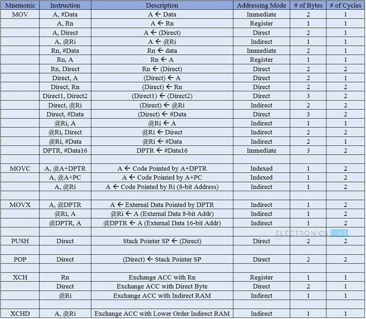
The Data Transfer Instructions are associated with transfer of data between registers or external program memory or external data memory. The Mnemonics associated with Data Transfer are given below.
MOV MOVC MOVX PUSH POP XCH XCHD
The following table lists out all the possible data transfer instructions along with other details like addressing mode, size occupied and number machine cycles it takes.
Arithmetic Instructions
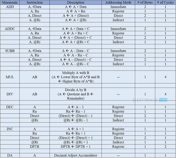
Using Arithmetic Instructions, you can perform addition, subtraction, multiplication and division. The arithmetic instructions also include increment by one, decrement by one and a special instruction called Decimal Adjust Accumulator. The Mnemonics associated with the Arithmetic Instructions of the 8051 Microcontroller Instruction Set are:
ADD ADDC SUBB INC DEC MUL DIV DA A
The arithmetic instructions have no knowledge about the data format i.e., signed, unsigned, ASCII, BCD, etc. Also, the operations performed by the arithmetic instructions affect flags like carry, overflow, zero, etc. in the PSW Register. All the possible Mnemonics associated with Arithmetic Instructions are mentioned in the following table.
Logical Instructions
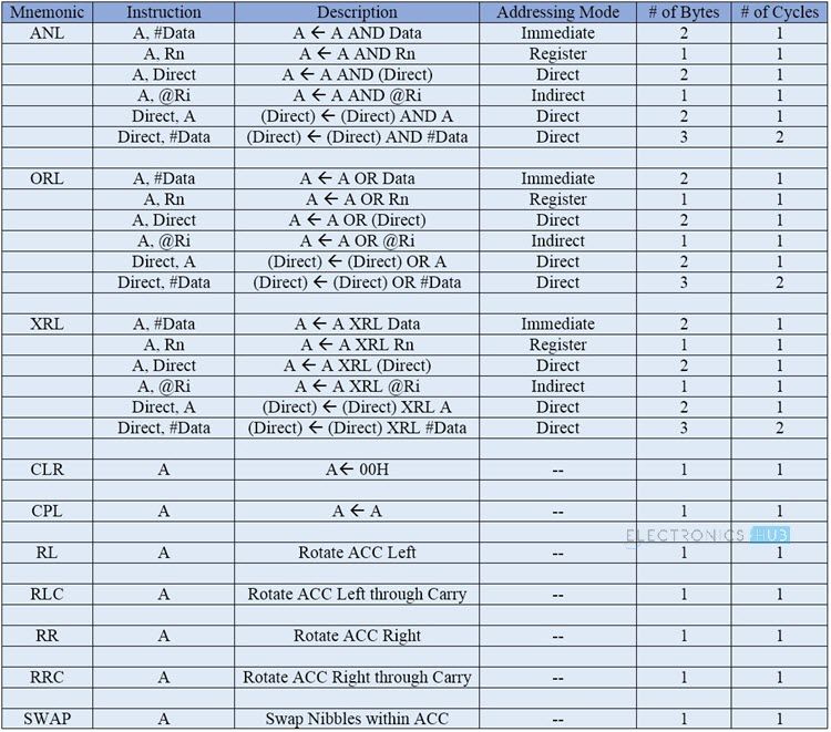
The next group of instructions are the Logical Instructions, which perform logical operations like AND, OR, XOR, NOT, Rotate, Clear and Swap. Logical Instruction are performed on Bytes of data on a bit-by-bit basis. Mnemonics associated with Logical Instructions are as follows:
ANL ORL XRL CLR CPL RL RLC RR RRC SWAP
The following table shows all the possible Mnemonics of the Logical Instructions.
Boolean or Bit Manipulation Instructions
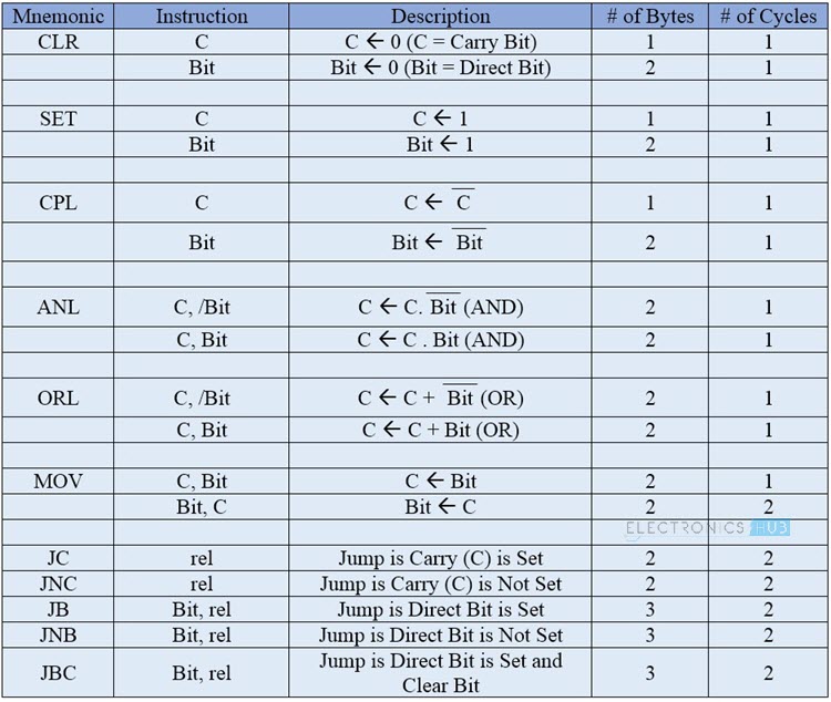
As the name suggests, Boolean or Bit Manipulation Instructions deal with bit variables. We know that there is a special bit-addressable area in the RAM and some of the Special Function Registers (SFRs) are also bit addressable. The Mnemonics corresponding to the Boolean or Bit Manipulation instructions are:
CLR SETB MOV JC JNC JB JNB JBC ANL ORL CPL
These instructions can perform set, clear, and, or, complement etc. at bit level. All the possible mnemonics of the Boolean Instructions are specified in the following table.
Program Branching Instructions
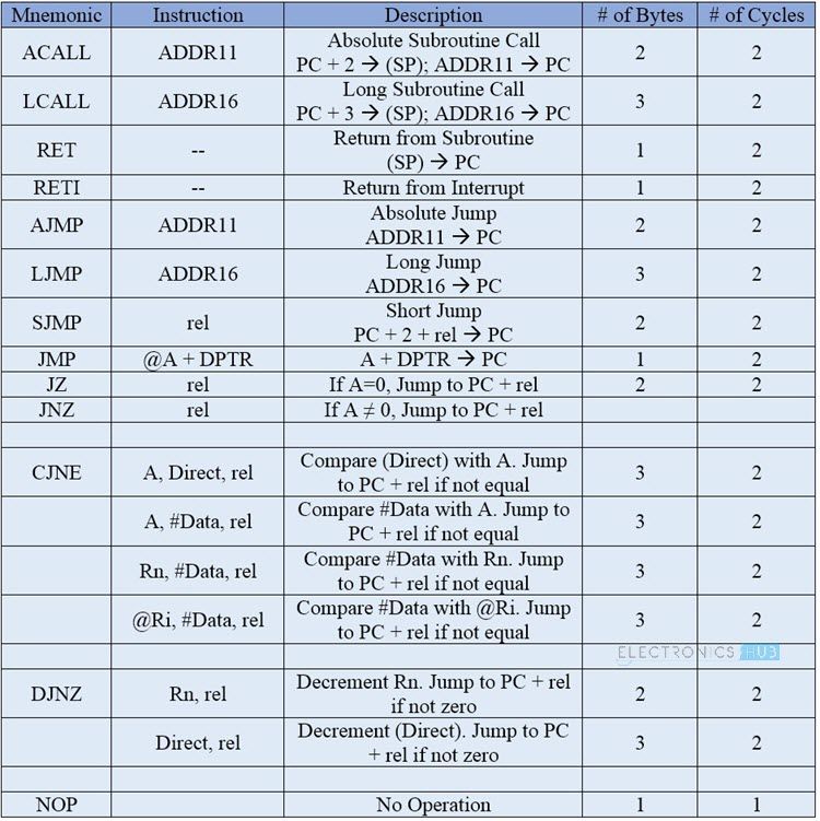
The last group of instructions in the 8051 Microcontroller Instruction Set are the Program Branching Instructions. These instructions control the flow of program logic. The mnemonics of the Program Branching Instructions are as follows.
LJMP AJMP SJMP JZ JNZ CJNE DJNZ NOP LCALL ACALL RET RETI JMP
All these instructions, except the NOP (No Operation) affect the Program Counter (PC) in one way or other. Some of these instructions has decision making capability before transferring control to other part of the program. The following table shows all the mnemonics with respect to the program branching instructions.
In this tutorial, we have seen the introduction to the 8051 Microcontroller Instruction Set, Addressing Modes in 8051 Microcontroller and different types of instructions in the Instruction Set of the 8051 Microcontroller. Logical Instructions is very useful infomation Comment * Name * Email * Website
Δ




![]()